E-mail: info@gem-cablesolution.com
 Address: No.8 Yuefeng Rd, High Tech Zone, Dongtai, Jiangsu, China | No.109 Qilin East Rd, Daning, Humen, Dongguan, Guangdong, China.
 English
  English
 русский
 日本語
日本語 Español
 عربى
عربى 中文简体
中文简体
Content
- 1 The Direct Answer: How Deep Are Cable Wires Buried?
- 2 Why Burial Depth Matters More Than Most People Think
- 3 Types of Underground Cables and Their Specific Depth Requirements
- 4 How Wire and Cable Extruder Technology Defines Underground Cable Performance
- 5 Regional Variations and Code Differences Beyond the NEC
- 6 Practical Installation Considerations When Burying Cable Wires
- 7 How Cable Construction From the Extruder Line Affects Burial Depth Selection
- 8 Common Mistakes That Lead to Buried Cable Failures
- 9 Depth Requirements for Specific Situations and Cable Runs
- 10 The Role of Ampacity and Heat in Determining Burial Depth for Power Cables
The Direct Answer: How Deep Are Cable Wires Buried?
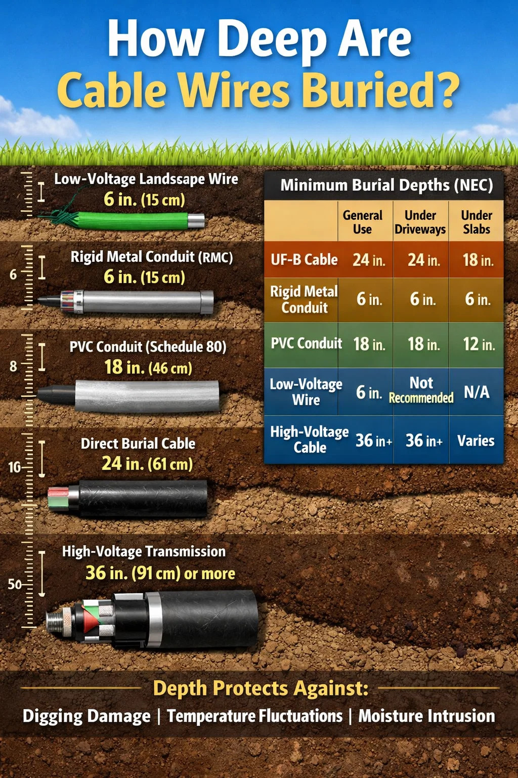
Cable wires are buried at depths ranging from 6 inches (15 cm) to 36 inches (91 cm) depending on cable type, application, voltage level, and local code requirements. In residential settings, low-voltage landscape wiring may sit just 6 inches below grade, while high-voltage transmission lines can be installed 36 inches or deeper. The National Electrical Code (NEC) in the United States establishes minimum burial depths that vary significantly by cable type and installation environment.
Understanding these depths is not just a matter of compliance — it directly affects safety, durability, and the long-term performance of the cable. Cables manufactured using a precision wire and cable extruder are engineered with specific insulation thicknesses and jacket materials designed to withstand the mechanical and environmental stresses of underground installation at these prescribed depths.
Below is a quick-reference summary of standard minimum burial depths according to NEC Table 300.5:
| Cable / Wiring Method | General Use (Residential) | Under Driveways / Roads | Under Concrete Slab |
|---|---|---|---|
| Direct Burial Cable (UF-B) | 24 inches (61 cm) | 24 inches (61 cm) | 18 inches (46 cm) |
| Rigid Metal Conduit (RMC) | 6 inches (15 cm) | 6 inches (15 cm) | 6 inches (15 cm) |
| PVC Conduit (Schedule 80) | 18 inches (46 cm) | 18 inches (46 cm) | 12 inches (30 cm) |
| Low-Voltage Landscape Wire | 6 inches (15 cm) | Not recommended | N/A |
| High-Voltage Transmission | 36 inches (91 cm) or more | 36+ inches (91+ cm) | Varies by utility spec |
Why Burial Depth Matters More Than Most People Think
Burial depth is not an arbitrary rule invented by code writers. It exists because cables face a complex set of physical threats once they are placed underground. Surface activity — foot traffic, vehicles, gardening tools, freeze-thaw cycles, burrowing animals — all generate mechanical forces that attenuate with depth. A cable sitting 6 inches below the surface of a lawn is at serious risk from a standard garden spade. That same cable at 24 inches is well protected.
Beyond mechanical damage, depth also governs thermal stability. Soil temperature fluctuates dramatically near the surface. In many North American climates, the top 12 inches of soil can swing from below freezing to over 30°C (86°F) between winter and summer. These temperature extremes cause cable insulation and jacket materials to expand, contract, and eventually crack or harden if they are not rated for such conditions. Cables produced by a modern wire and cable extruder use cross-linked polyethylene (XLPE) or specialized PVC compounds that resist thermal degradation, but even these materials benefit from the buffered temperature environment that greater burial depth provides.
Moisture is another critical factor. At shallow depths, cables are exposed to percolating surface water, irrigation, and pooling. While direct burial cables are waterproof by design, repeated wet-dry cycling over years still degrades connectors, terminations, and unsealed sections. Utilities and contractors who install infrastructure cables at 30 to 36 inches report significantly lower incidence of moisture-related failures compared to residential installations at minimum code depths.
Types of Underground Cables and Their Specific Depth Requirements
Not all cables are created equal, and the differences in construction — directly attributable to how they are manufactured using different wire and cable extruder configurations — translate directly into different depth requirements and burial suitability.
UF-B (Underground Feeder) Cable
UF-B cable is the most common direct-burial cable used in residential construction in the United States. The "B" designation indicates it is suitable for underground burial without conduit. Its conductors are individually insulated, then the entire assembly is encased in a solid thermoplastic jacket that resists moisture, fungi, and corrosion. The NEC requires UF-B to be buried at a minimum of 24 inches when run without conduit. This depth provides adequate protection from routine digging activity and surface loads.
Typical applications include outdoor outlet circuits, garage subpanels, outbuilding feeds, and garden lighting at higher voltages. A 12/2 UF-B cable feeding a 20-amp outdoor circuit to a detached garage must be buried the full 24 inches for the entire run — including under any landscaping, pathways, or grass.
THWN/THHN Wire in Conduit
THWN and THHN are individual conductors intended for use inside conduit — they are not rated for direct burial alone. However, when installed in rigid metal conduit (RMC), the NEC permits a burial depth of just 6 inches. This is because the conduit itself provides the mechanical protection that depth would otherwise supply. RMC in a 6-inch trench is far more resistant to a shovel strike than bare cable at 24 inches.
Schedule 80 PVC conduit offers a middle ground — more impact-resistant than Schedule 40, it requires a minimum burial of 18 inches. Schedule 40 PVC conduit, the most commonly available type, must be buried at 18 inches in general use and 12 inches under concrete.
Low-Voltage Landscape and Irrigation Cables
Cables operating below 30 volts — such as those used for garden path lighting, landscape speakers, and drip irrigation controllers — are permitted to be buried at just 6 inches. The logic here is that the low voltage presents minimal shock hazard. Even so, 6 inches is barely sufficient to escape most garden tools. Many professional landscapers bury low-voltage cable at 8 to 10 inches as a practical margin of safety, especially in areas subject to cultivation.
Telecommunications and Data Cables
Buried telephone, fiber optic, and data cables follow their own standards, typically set by the installing utility or the Telecommunications Industry Association (TIA). Fiber optic cables are often buried at 18 to 36 inches, with deeper installation required under roads and driveways. These cables are produced using highly specialized wire and cable extruder systems that apply multiple buffer layers, strength members, and outer jackets optimized for ground contact and rodent resistance.
High-Voltage Utility Transmission Cables
Underground transmission cables carrying voltages above 2,000 volts are governed by utility engineering specifications rather than the residential NEC. Typical burial depths range from 36 inches to 60 inches (91 to 152 cm), and in some urban duct bank installations, the top of the duct bank may sit 30 inches below grade with cables inside running deeper still. These cables are among the most complex products manufactured on large-scale wire and cable extruder lines, featuring XLPE insulation, metallic shielding, armoring, and multi-layer outer jackets.
How Wire and Cable Extruder Technology Defines Underground Cable Performance
The ability of a cable to survive at any burial depth depends almost entirely on how it was manufactured. A wire and cable extruder is the core machine in cable production — it melts thermoplastic or thermoset compounds and applies them uniformly over conductors under precisely controlled temperature, pressure, and speed conditions. The quality of this process determines insulation thickness consistency, jacket adhesion, void-free cross-sections, and resistance to environmental stressors.
Extruder Types Used in Underground Cable Production
Several categories of wire and cable extruder are used depending on the insulation material and cable type:
- Single-screw extruders — The most common configuration for applying PVC, polyethylene, or TPE jackets to cables. A rotating screw melts and conveys compound through a die at the conductor. They are used for UF-B outer jacket application, low-voltage landscape cable, and general-purpose wiring.
- Tandem and triple-head extruder lines — Used for multi-layer cable construction, where insulation, semiconducting layers, and outer jackets must be applied in sequence or simultaneously. These are essential for producing medium-voltage and high-voltage underground cables where layer integrity directly affects dielectric performance.
- CV (continuous vulcanization) lines — A specialized wire and cable extruder system used for XLPE-insulated cables. After extrusion, the cable passes through a heated tube filled with nitrogen or steam where crosslinking occurs. XLPE produced this way can withstand conductor temperatures up to 90°C continuously and up to 250°C under short-circuit conditions — properties essential for buried transmission cables.
- Catenary continuous vulcanization (CCV) lines — A variant where the cable passes through a catenary-shaped tube, relying on gravity to maintain cable geometry during crosslinking. These are used for the most demanding high-voltage cables, including those buried at 36 inches or more for grid infrastructure.
Insulation Materials and Burial Suitability
The compound fed into a wire and cable extruder determines the final cable's suitability for specific burial depths and environments:
| Material | Max Temp Rating | Moisture Resistance | Typical Application |
|---|---|---|---|
| PVC (Polyvinyl Chloride) | 75°C (167°F) | Good | UF-B, control cables, low-voltage landscape |
| XLPE (Cross-Linked PE) | 90°C (194°F) | Excellent | Medium/high-voltage underground transmission |
| LLDPE / HDPE | 75–90°C | Excellent | Fiber optic buffer tubes, data cable outer jackets |
| EPR (Ethylene Propylene Rubber) | 90°C (194°F) | Excellent | Mining cables, power station feeders, wet locations |
| Nylon (Polyamide) Jacket | 60–75°C | Good | THHN conductors in conduit systems |
A wire and cable extruder must maintain extremely tight tolerances on wall thickness — typically ±5% or better for power cables — because uneven insulation creates localized electrical stress points that can lead to dielectric failure years after installation. For cables buried at depth, detecting and repairing such failures is expensive and disruptive, making manufacturing quality at the extruder stage the single most important factor in long-term buried cable reliability.
Regional Variations and Code Differences Beyond the NEC
The NEC provides a baseline for burial depth in the United States, but it is not the only applicable standard — and in many cases it is not even the most stringent one. Local amendments, state regulations, utility easement requirements, and international standards can all increase the required burial depth beyond NEC minimums.
US Local Amendments
Many jurisdictions adopt the NEC with local amendments. California, for example, has additional requirements through Title 24 that can require deeper burial in certain applications. Some municipalities in the northern states require deeper burial to account for frost line depth — in Minnesota or Maine, where frost penetration can reach 48 to 60 inches, utilities and some residential codes push burial depths well beyond NEC minimums to prevent freeze-related damage.
International Standards
Outside the United States, underground cable depth requirements vary considerably:
- United Kingdom (BS 7671 / IET Wiring Regulations): Cables in gardens should be buried at a minimum of 450mm (approximately 18 inches), while cables under roads require 600mm (approximately 24 inches) with additional mechanical protection such as cable tiles or warning tape.
- Germany (DIN VDE standards): Power cables are generally buried at 600mm minimum, with 1000mm (approximately 39 inches) required under roadways and public areas.
- Australia (AS/NZS 3000): Minimum depths range from 500mm for cables in conduit in gardens to 900mm for cables under vehicle access areas.
- China (GB standards): Low-voltage underground cables are typically required at 700mm, while high-voltage cables must be at 1000mm or deeper in urban areas.
These differences reflect not just regulatory tradition but also soil conditions, traffic loading, and the nature of local ground disturbance activity. Countries with dense urban infrastructure tend toward deeper requirements because the consequences of cable damage — disrupted power to thousands of people — justify the added installation cost.
Practical Installation Considerations When Burying Cable Wires
Knowing the required depth is only the starting point. Executing a buried cable installation correctly involves a series of decisions and precautions that determine whether the cable performs reliably for its intended 20 to 40-year service life.
Trench Preparation and Bedding
The quality of the trench bed matters almost as much as depth. Cables should never rest on rocky or uneven soil that could create point contact stress over time. Standard practice calls for a 3-inch (75mm) bed of fine sand or screened soil below the cable, with a similar cover of sand above it before the trench is backfilled with native soil. For high-voltage cables, this sand bed may be 6 inches (150mm) or more. This is specified not just for mechanical protection but because compacted, uniform backfill provides more consistent thermal conductivity — important for cables where heat dissipation from current flow affects ampacity ratings.
Warning Tape and Marking Systems
At a depth of 12 inches above the cable, installers should place detectable underground warning tape. This bright plastic tape — typically yellow for electrical, orange for communications — alerts future diggers before they reach the cable. For high-value or high-voltage installations, magnetically detectable tape or tracer wire is added to allow electronic locating with a cable locator instrument without excavation.
Depth Reduction Strategies Using Conduit
Where digging to the full 24-inch depth is impractical — such as through established landscaping, under patios, or near tree roots — switching to rigid metal conduit allows the burial depth to drop to just 6 inches. This is a legitimate and widely used strategy. The conduit must be properly waterproofed at joints and must have appropriate entry and exit fittings. Any point where a cable transitions from conduit to direct burial must be managed carefully, as this junction is a common failure point.
Call Before You Dig
Before digging any trench for cable burial, contacting a utility locating service is not optional — it is legally required in most jurisdictions. In the United States, calling 811 (the national "Call Before You Dig" number) triggers the marking of all underground utilities in the work area within 2 to 3 business days. Utility cables — gas, electric, water, telecom — may be buried at depths that differ from what standards require because they were installed under older codes, by different contractors, or in non-standard configurations. Existing underground cables are routinely found at depths between 12 and 18 inches even when current code would require 24 inches.
Splices and Connections Below Grade
The NEC permits direct burial splices for UF-B cable provided they are made with listed underground splice kits — waterproof gel-filled connectors or heat-shrink assemblies that maintain the cable's burial rating at the joint. However, industry best practice strongly discourages underground splices whenever possible. Each splice is a potential weak point. Long cable runs should use continuous lengths from an accessible junction box or pull box at surface level whenever the run length permits. Junction boxes installed in-ground must be rated for wet or damp locations and kept accessible.
How Cable Construction From the Extruder Line Affects Burial Depth Selection
An installer choosing between different cable products for a buried application is, in effect, choosing between different manufacturing philosophies. A cable produced on a high-precision wire and cable extruder line with tight process controls will have more uniform insulation, better jacket adhesion, and more consistent electrical and mechanical performance than one produced at lower quality standards — even if both technically carry the same rating and listing.
For example, two UF-B cables with the same AWG and voltage rating may differ significantly in:
- Jacket concentricity — How centered the conductor is within the insulation. Poor concentricity from inconsistent extruder die alignment creates thin spots that are vulnerable to dielectric breakdown.
- Jacket thickness uniformity — An outer jacket that varies from 0.8mm to 1.4mm around its circumference provides uneven mechanical protection. Premium cables produced on CNC-controlled extruder lines hold jacket thickness within ±0.05mm.
- Material compound quality — The specific PVC or PE compound formulation, including UV stabilizers, plasticizer type, and filler content, directly affects how the cable holds up in buried environments over time. Cheaper compounds may pass initial listing tests but degrade faster in real soil environments.
- Conductor quality — Oxygen-free or high-conductivity copper drawn to precise tolerances resists oxidation better than lower-grade copper, especially at buried splice points and terminations where long-term contact resistance buildup can cause overheating.
When selecting cable for a burial application — particularly one that will be difficult to access after installation — cable provenance and manufacturing quality are legitimate selection criteria, not just marketing considerations. Cables from manufacturers who invest in modern wire and cable extruder technology, in-line spark testing, and eccentricity monitoring systems offer measurably better long-term underground performance.
Common Mistakes That Lead to Buried Cable Failures
The majority of buried cable failures in residential and light commercial applications are attributable to a small set of installation errors rather than product defects. Understanding these failure modes helps explain why burial depth requirements exist and why adhering to them strictly is important.
- Insufficient depth: The single most common mistake. Homeowners and sometimes contractors bury cable at 12 or even 8 inches to save time, only to have the cable damaged by routine yard work within a few years. A single spade cut through a buried 12/2 UF-B feeding an outdoor outlet can create a fault that trips breakers, damages connected equipment, or in the worst case starts a fire if the overcurrent protection fails to operate correctly.
- Using the wrong cable type: Standard NM-B (Romex) is indoor cable and is not listed for direct burial, yet it is found in buried installations regularly. NM-B lacks the solid thermoplastic jacket of UF-B and will degrade rapidly when exposed to soil moisture — typically within 2 to 5 years.
- Inadequate backfill: Backfilling directly with rocky or clay soil without sand bedding creates mechanical point stresses and, in clay soils, waterlogging around the cable that accelerates jacket degradation.
- Skipping protection at transitions: Where buried cable enters a building or transitions from underground to above-grade, it must be protected by conduit extending at least 8 inches above finished grade. Unprotected cable at grade-level transitions is highly vulnerable to physical damage, UV degradation, and moisture infiltration.
- No documentation of cable routes: Failing to photograph or sketch cable routes before backfilling means future homeowners or contractors have no way to know where cables are buried without a locating service — and locating services cannot always find small residential cables at shallow depth.
Depth Requirements for Specific Situations and Cable Runs
Different locations within a single installation can require different burial depths, which means a single cable run across a property may need to change depth as it crosses different terrain types.
Under Lawns and Gardens
UF-B at 24 inches is the standard for lawn areas. This depth clears typical lawn aeration equipment, dethatchers, and most garden tools. However, raised garden beds that will be regularly dug to 12 or 18 inches present a risk. Routing cable around rather than under planting beds is strongly recommended.
Under Driveways and Vehicle Access Areas
UF-B under driveways still requires 24 inches. However, many installers transition to rigid conduit for driveway crossings both to add mechanical protection against vehicular loading and to allow future cable replacement without excavating through the driveway surface. A conduit sleeve under the driveway installed during driveway construction costs very little; adding one after the fact may cost $500 to $2,000 in concrete or asphalt cutting and restoration.
Under Concrete Slabs
When a cable passes under an existing or planned concrete slab (not a driveway), UF-B may be buried at 18 inches and PVC conduit at 12 inches. The slab itself provides significant mechanical protection, justifying the reduced depth. Cables under slabs should be installed in conduit whenever possible to allow replacement — a cable failure under a concrete floor is extremely costly to repair if the cable is direct-buried.
Inside Conduit Under Irrigation-Controlled Areas
In commercial landscaping installations with automatic irrigation, buried cable zones are frequently disturbed for irrigation repairs. Specifying conduit and increasing burial depth to 30 inches in these areas significantly reduces the risk of inadvertent cable damage during irrigation maintenance — a common and expensive failure mode in commercial property management.
The Role of Ampacity and Heat in Determining Burial Depth for Power Cables
For power cables carrying significant current, burial depth interacts with ampacity — the maximum current a cable can carry without exceeding its temperature rating. Underground cables dissipate heat into surrounding soil rather than air, and soil thermal resistivity varies with moisture content, compaction, and composition. The NEC ampacity tables for underground cables assume specific soil thermal resistivity values and burial depths.
A cable buried at 24 inches in typical soil can typically carry more current than the same cable buried at 6 inches, because deeper soil maintains more stable and generally lower temperatures, improving heat dissipation. Utility engineers performing detailed ampacity calculations for underground feeders account for burial depth as a primary variable. For a 500 kcmil XLPE-insulated cable — produced on a large-diameter wire and cable extruder line — the difference between burial at 30 inches versus 18 inches in dry sandy soil can represent a 10 to 15% increase in allowable ampacity, which translates directly into capacity to serve more load without requiring a larger and more expensive conductor.
This is why utility-grade cable installation specifications routinely call for depths well beyond code minimums. The extra depth is not merely caution — it is engineering optimization that maximizes the return on conductor material investment while extending service life by keeping operating temperatures lower.