E-mail: info@gem-cablesolution.com
 Address: No.8 Yuefeng Rd, High Tech Zone, Dongtai, Jiangsu, China | No.109 Qilin East Rd, Daning, Humen, Dongguan, Guangdong, China.
 English
  English
 русский
 日本語
日本語 Español
 عربى
عربى 中文简体
中文简体
Content
- 1 How Does Coax Work: The Short Answer
- 2 The Physical Structure of a Coaxial Cable, Layer by Layer
- 3 Characteristic Impedance: Why 50 Ω and 75 Ω Dominate
- 4 Signal Transmission Mechanics Inside the Cable
- 5 How Coaxial Cable Is Manufactured: The Role of the Wire and Cable Extruder
- 6 Common Coaxial Cable Types and Their Specifications
- 7 Connectors and Termination: Where Most Problems Start
- 8 Coax vs. Other Transmission Media: When to Choose It
- 9 Quality Control in Coaxial Cable Production
- 10 Real-World Applications That Show How Coax Works in Practice
- 11 Frequently Asked Questions About How Coax Works
How Does Coax Work: The Short Answer
Coaxial cable transmits electrical signals using two concentric conductors — a solid inner conductor surrounded by a tubular outer conductor (shield) — separated by a dielectric insulator and wrapped in a protective outer jacket. The geometry keeps the signal confined within the cable, drastically reducing electromagnetic interference (EMI) and signal loss compared to standard twisted-pair or parallel wire. This is why coax remains the go-to choice for RF transmission, broadband internet, cable television, and precision instrumentation, even as fiber and wireless alternatives expand.
Every layer of a coaxial cable has a specific physical and electrical purpose. The conductor carries current; the dielectric controls impedance and propagation speed; the shield blocks noise; the jacket protects against mechanical and environmental damage. Strip away any one layer and the cable stops functioning correctly. Understanding each layer — and how they interact — explains why coax engineering is more demanding than it appears.
The Physical Structure of a Coaxial Cable, Layer by Layer
Inner Conductor
The center conductor is typically solid or stranded copper, though copper-clad steel (CCS) and silver-plated copper are used in high-frequency or high-strength applications. Diameter ranges from under 0.5 mm in miniature RF cables to over 10 mm in large CATV trunk cables. At high frequencies, current travels near the surface of the conductor — a phenomenon called the skin effect — so the conductor's surface quality and conductivity directly affect loss figures. Silver plating raises surface conductivity, which is why microwave-grade cables often use it.
Dielectric Insulator
Sandwiched between the inner and outer conductors, the dielectric controls two critical parameters: impedance and velocity of propagation (VoP). Common dielectric materials include solid polyethylene (PE), foam polyethylene, polytetrafluoroethylene (PTFE), and air-spaced designs. Foam PE lowers dielectric constant from roughly 2.25 (solid PE) to around 1.4–1.6, which raises VoP from about 66% to 78–85% of the speed of light and simultaneously reduces dielectric loss — both desirable for broadband or long-run applications. PTFE is chosen when temperature stability matters; it holds its electrical properties from –65 °C to +200 °C.
The thickness and uniformity of the dielectric layer directly set the cable's characteristic impedance. Even slight eccentricity — off-center placement of the inner conductor — shifts impedance and creates reflections. This is why wire and cable extruder precision matters so much in manufacturing: the cross-head die must center the conductor within a tolerance measured in micrometers.
Outer Conductor (Shield)
The shield serves two functions simultaneously: it is the return-current path for the signal, and it is the electromagnetic barrier that prevents external noise from coupling into the cable. Common shield constructions include:
- Solid aluminum or copper tube — used in hard-line CATV cables; near-100% coverage, very low loss, rigid
- Braided shield — typically 85–98% optical coverage; flexible, durable, used in RG-58, RG-6, RG-11
- Foil + braid combination — foil provides 100% coverage; braid adds mechanical strength and DC continuity; common in satellite and broadband cables
- Tri-shield and quad-shield — multiple foil and braid layers for high-interference environments; shielding effectiveness can exceed 90 dB
Outer Jacket
The jacket is the outermost protective layer, commonly made from PVC, polyethylene, LSZH (low smoke zero halogen), or fluoropolymers. Jacket material choice is driven by installation environment: PVC is economical and flame-retardant for indoor use; PE and LLDPE offer UV and moisture resistance for outdoor burial; LSZH is mandated in public spaces and transportation infrastructure due to reduced toxic gas emission in fires. The jacket is applied by a wire and cable extruder in a separate extrusion pass after the shield is complete.
Characteristic Impedance: Why 50 Ω and 75 Ω Dominate
Characteristic impedance is not a DC resistance — it is a frequency-independent property determined entirely by the geometry of the cable and the dielectric constant of the insulator. The formula is:
Z₀ = (138 / √εr) × log₁₀(D/d)
Where εr is the relative permittivity of the dielectric, D is the inner diameter of the outer conductor, and d is the outer diameter of the inner conductor. Two impedance values dominate the coaxial world for well-established engineering reasons:
| Parameter | 50 Ω Coax | 75 Ω Coax |
|---|---|---|
| Optimized for | Power handling | Minimum signal loss |
| Typical applications | RF transmitters, antennas, test equipment, Ethernet (10BASE2) | CATV, satellite, HDTV, broadband distribution |
| Common cable types | RG-58, RG-8, LMR-400 | RG-6, RG-11, RG-59 |
| Attenuation at 1 GHz (typical) | ~5–6 dB/100m (RG-58) | ~4–5 dB/100m (RG-6) |
The theoretical minimum-loss impedance for a coax with polyethylene dielectric is approximately 77 Ω — which is why 75 Ω became the broadcast industry standard. The 50 Ω value is a compromise between maximum power handling (~30 Ω optimum) and minimum loss, making it better suited for two-way RF links. Mismatching impedance between source, cable, and load causes signal reflections, standing waves, and power loss — problems quantified by the voltage standing wave ratio (VSWR).
Signal Transmission Mechanics Inside the Cable
Coaxial cable does not transmit signals the way most people intuitively imagine. The energy does not flow through the conductor the way water flows through a pipe. Instead, it propagates as an electromagnetic wave in the space between the inner and outer conductors — the dielectric region. The conductors act as boundary conditions that guide and confine the wave. This mode of propagation is called the TEM (transverse electromagnetic) mode, in which both the electric and magnetic field components are entirely transverse to the direction of travel.
The electric field radiates radially between the inner conductor (+) and the outer conductor (–), while the magnetic field forms concentric circles around the inner conductor. Because the field is entirely enclosed within the shield, the cable radiates almost no energy outward and is almost immune to external fields — as long as the shield integrity is maintained. A break in the shield, a poor connector, or a kinked cable disrupts the field geometry and introduces noise and loss.
Velocity of Propagation and Electrical Length
Signals travel through coax at a speed that is a fraction of the speed of light in vacuum, determined by the dielectric. Solid PE gives a VoP of about 66%; foam PE raises it to 78–85%; PTFE air-spaced designs can reach 93–98%. For a 10-meter cable with solid PE, the one-way signal delay is roughly 50 nanoseconds. This matters in precision timing, radar systems, and phased array antennas, where cable lengths are cut to specific electrical lengths — fractions or multiples of the signal wavelength — to achieve controlled phase relationships.
Attenuation Mechanisms
Signal loss in coax comes from three main sources:
- Conductor loss — resistive heating in the inner conductor and shield, dominant at lower frequencies and proportional to √f due to skin effect
- Dielectric loss — energy absorbed by the insulator as the alternating field stresses its molecular structure; grows linearly with frequency and is why low-loss dielectrics like PTFE and foam PE are used at microwave frequencies
- Radiation loss — leakage through shield imperfections; generally negligible in well-constructed cables but significant if the shield is damaged or if higher-order propagation modes are excited above the cable's cutoff frequency
Attenuation is specified in dB per unit length at specific frequencies. A standard RG-6 quad-shield cable has roughly 2.0 dB/100 ft at 100 MHz and 6.5 dB/100 ft at 900 MHz, illustrating how loss increases significantly with frequency. High-end low-loss cables like LMR-400 cut 900 MHz attenuation to around 2.7 dB/100 ft through larger conductors and foam dielectric.
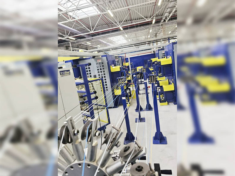
How Coaxial Cable Is Manufactured: The Role of the Wire and Cable Extruder
Manufacturing coaxial cable is a multi-step process where dimensional precision at each stage determines the cable's electrical performance. A wire and cable extruder is central to two of the most critical steps: dielectric insulation and outer jacket application.
Inner Conductor Drawing and Stranding
The process begins with copper rod drawn through a series of dies to reach the target conductor diameter. Tolerances are tight: for a 50 Ω cable with a 0.9 mm conductor, even a ±0.01 mm deviation shifts impedance noticeably. Stranded conductors go through a bunching or stranding machine before the extrusion line.
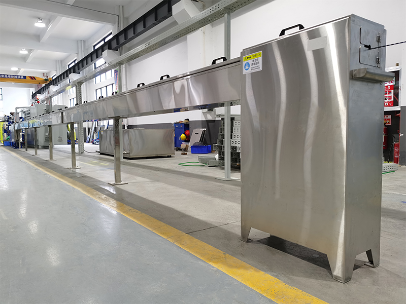
Dielectric Extrusion
This is where the wire and cable extruder performs its most critical function. The conductor is fed through a cross-head die, and melted PE, foam PE, or PTFE compound is applied around it under controlled pressure and temperature. The concentricity of the dielectric — how precisely centered the conductor is within the insulation — must be maintained to within ±1–2% of the dielectric wall thickness to keep impedance within specification.
For foam PE cables, gas (typically nitrogen) is injected into the molten polymer stream to create a controlled cellular structure. Foam density directly sets the dielectric constant, so gas pressure, melt temperature, and line speed must be tightly coordinated. Modern cable extruder lines use real-time capacitance measurement after the die — measuring capacitance per unit length gives an immediate indication of insulation diameter and dielectric constant, allowing automatic feedback to the extruder's control system.
After extrusion, the insulated conductor passes through a water-cooling trough to solidify the dielectric before it reaches the caterpillar haul-off unit. Line speeds for small-diameter coax dielectric extrusion typically range from 100 to over 500 meters per minute, depending on conductor size and dielectric thickness.
Shielding
After the dielectric cools and is spooled, the cable goes to a shielding line. Foil shields are applied by wrapping aluminum-polyester laminate tape longitudinally or helically over the dielectric. Braided shields are applied on a braiding machine with dozens to hundreds of bobbins carrying fine copper or tinned-copper wire. For cables requiring foil-plus-braid construction, both operations may be combined on a single machine pass.
Jacket Extrusion
The final extrusion step applies the outer jacket using another wire and cable extruder — typically a single-screw or twin-screw machine depending on the compound. PVC jacketing lines commonly operate at 50–150 m/min; PE and LSZH compounds require careful temperature profiling along the extruder barrel to prevent degradation. Jacket wall thickness uniformity is checked by spark testing (high-voltage continuity testing at 2–6 kV) and laser diameter gauges inline. Finished cables are printed with type designation, impedance, voltage rating, and manufacture date for field identification.
Common Coaxial Cable Types and Their Specifications
The "RG" designation (Radio Guide) was originally a U.S. military specification system. While many RG designations have been superseded by manufacturer-specific part numbers for modern cables, the legacy designations remain widely recognized in the industry. Understanding the differences helps in selecting the right cable for a given application.
| Cable Type | Impedance | Dielectric | OD (approx.) | Typical Use |
|---|---|---|---|---|
| RG-58 | 50 Ω | Solid PE | 4.95 mm | Ham radio, thin Ethernet, test cables |
| RG-8 / LMR-400 | 50 Ω | Foam PE | 10.3 mm | Long antenna runs, base stations |
| RG-59 | 75 Ω | Solid PE | 6.15 mm | CCTV, short CATV runs (mostly replaced by RG-6) |
| RG-6 | 75 Ω | Foam PE | 6.86 mm | CATV, satellite, broadband |
| RG-11 | 75 Ω | Foam PE | 10.5 mm | Long distribution runs, trunk lines |
| Semi-rigid (UT-141) | 50 Ω | PTFE | 3.58 mm | Microwave modules, PCB interconnects |
Connectors and Termination: Where Most Problems Start
The cable itself is only part of a coaxial link. The connector transitions the signal from cable to equipment and, if poorly made or installed, becomes the dominant source of signal loss, reflection, and failure. The connector must maintain the same characteristic impedance as the cable across its internal geometry — any discontinuity causes a reflection.
Common Coax Connector Types
- BNC (Bayonet Neill–Concelman) — 50 Ω, rated to ~4 GHz, quarter-turn bayonet lock; standard in test equipment, video, and instrumentation
- SMA (SubMiniature version A) — 50 Ω, rated to 18 GHz, threaded; widely used in RF modules, antennas, and microwave assemblies
- N-type — 50 Ω or 75 Ω, rated to 11–18 GHz, weatherproof; used in outdoor antennas and base station equipment
- F-type — 75 Ω, up to ~3 GHz; ubiquitous in residential CATV and satellite installations; the center conductor of the cable itself serves as the connector pin
- PL-259 (UHF) — nominally 50 Ω but not truly constant impedance; rated to ~300 MHz in practice; common in amateur radio
Proper termination requires stripping the cable to exact dimensions, not crushing the braid, maintaining the dielectric's concentricity at the connector interface, and applying the correct torque when mating. A single improperly installed F-connector in a cable TV distribution system can cause signal ingress (outside signals leaking in) and signal egress (cable signals leaking out), degrading the entire node's performance.
Coax vs. Other Transmission Media: When to Choose It
Coaxial cable is not the right choice for every application, but it retains clear advantages in specific scenarios. Comparing it against common alternatives clarifies where it fits best.
Coax vs. Twisted Pair (Cat5e/Cat6/Cat8)
Twisted pair relies on differential signaling and tight twist rates to cancel EMI — a fundamentally different approach from coax's shielded TEM mode. Twisted pair dominates structured Ethernet cabling because it is cheaper, lighter, and easier to terminate. However, it cannot match coax at RF frequencies above a few hundred MHz or in high-interference environments. Cat8 supports 40 Gbps but only over 30-meter runs at 2 GHz; a properly installed RG-6 coax handles broadband signals to 3 GHz over much longer distances with far simpler amplification.
Coax vs. Fiber Optic
Fiber offers essentially zero electromagnetic interference susceptibility, much lower attenuation over long distances (~0.2 dB/km for single-mode vs. 40–100 dB/km for coax at microwave frequencies), and bandwidth capacity that dwarfs copper. The tradeoffs are cost of transceiver electronics, fragility, and inability to carry DC power alongside the signal. Coax remains preferred for short RF links, antenna feed lines, and applications requiring power + signal on one cable (e.g., phantom-powered microphones, active satellite LNBs fed via coax).
Coax vs. Waveguide
At frequencies above roughly 18 GHz, coax losses become prohibitive, and waveguide — a hollow metal pipe carrying EM waves — offers much lower attenuation. Waveguide has no inner conductor and therefore no conductor loss at the center; its rigid structure and frequency-selective nature (waveguide only passes signals above its cutoff frequency) make it unsuitable for broadband or flexible installation. Coax dominates below 18 GHz wherever flexibility and connectivity are needed.
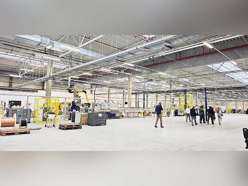
Quality Control in Coaxial Cable Production
The precision demands of coaxial cable manufacturing make quality control a continuous, inline process rather than a batch inspection at the end. A wire and cable extruder line for coax production typically integrates multiple measurement systems simultaneously:
- Laser diameter gauges — non-contact measurement of dielectric OD, typically accurate to ±0.001 mm; placed immediately after the cooling trough
- Capacitance monitors — measure capacitance per unit length, which correlates to dielectric wall thickness and dielectric constant; deviations trigger automatic line speed or extruder RPM corrections
- Eccentricity scanners — X-ray or ultrasonic scanners check concentricity of the inner conductor within the dielectric in real time
- Spark testers — apply 2–10 kV DC or AC across the dielectric to detect any pinholes or thin spots that would cause insulation failure in service
- Finished cable TDR testing — time-domain reflectometry identifies impedance discontinuities along the finished cable by sending a pulse down the line and analyzing reflections
Impedance uniformity specifications for broadcast-grade CATV cable are typically ±2 Ω over the full cable length, with structural return loss (SRL) requirements of 23–30 dB in the 5–1000 MHz band. Achieving these numbers consistently at production speeds above 200 m/min requires extremely precise die design, material consistency, and closed-loop process control — all centered on the performance of the wire and cable extruder and its associated measurement systems.
Real-World Applications That Show How Coax Works in Practice
Cable Television (CATV) Distribution
A CATV head-end receives signals and distributes them over a hybrid fiber-coaxial (HFC) network. Fiber carries the signal from the head-end to neighborhood nodes; RG-11 or hard-line coax carries it from the node to the tap (typically within 500 meters); RG-6 drops connect from the tap to individual homes. Each segment uses amplifiers to overcome cable attenuation, spaced based on the cable's loss at the highest carrier frequency — typically 1 GHz or higher in DOCSIS 3.1 systems.
Cellular Base Stations
The feeder cable between a BTS radio unit and the antenna at the top of a tower is almost always coaxial — either flexible corrugated coax or rigid hard-line. A 30-meter LMR-400 run at 900 MHz loses roughly 0.8 dB; at 2.1 GHz (3G UMTS), the same run loses about 1.3 dB. Every dB of feeder loss directly reduces effective radiated power, which is why remote radio head (RRH) installations that mount the radio unit at the top of the tower — connected to the baseband unit by fiber — have become dominant: they eliminate the feeder loss entirely.
Medical and Industrial Instrumentation
Ultrasound transducers, MRI signal chains, and industrial radar level gauges all rely on coaxial connections for the same reason as broadcast systems: shielding integrity and controlled impedance. In ultrasound, the coax carries MHz-range pulses to and from piezoelectric transducers with minimum distortion. The dielectric and conductor materials must be biocompatible in some cases, and the cable must survive sterilization cycles — requirements that push designs toward specialty fluoropolymer dielectrics produced on dedicated wire and cable extruder lines.
GPS and Satellite Receivers
GPS operates at 1575.42 MHz (L1) and 1227.60 MHz (L2). The coaxial run from an active GPS antenna to a receiver feeds both the RF signal and the DC power for the antenna's built-in LNA over the same cable. Cable loss directly degrades the signal-to-noise ratio. A 10-meter RG-6 run at 1.5 GHz introduces roughly 1.0 dB of loss — manageable; a 50-meter run would consume nearly 5 dB, typically exceeding the LNA gain of a standard active antenna and requiring a powered signal booster inline.
Frequently Asked Questions About How Coax Works
Why does coaxial cable have such good EMI rejection?
Because the electromagnetic field carrying the signal is entirely enclosed between the inner and outer conductors. External fields cannot penetrate a continuous shield — they induce currents on the outer surface of the shield, but those currents do not affect the internal field. The reverse is also true: the cable's internal signal field does not radiate outward, preventing interference with other systems. This "coaxial symmetry" is the fundamental reason coax outperforms open-wire or twisted-pair in RF environments.
What happens if you use the wrong impedance cable?
Using a 75 Ω cable in a 50 Ω system creates an impedance mismatch. Some of the signal power is reflected back toward the source at every transition — at the input and at the output. The reflected and incident waves combine to create standing waves on the cable, which means signal amplitude varies along the cable length instead of being constant. A VSWR of 1.5:1 (a modest mismatch from a 50/75 Ω junction) represents about 4% reflected power. In high-power RF transmitters, excessive reflected power can damage the final-stage amplifier. In precision measurement, it introduces errors in the measured signal.
Can you run power and signal through coax at the same time?
Yes. This is called Power over Coax (PoC) or, in the satellite context, LNB powering. A DC voltage (typically 13 V or 18 V for satellite LNBs; varies for CCTV) is superimposed on the inner conductor alongside the RF signal. A bias tee — a simple inductor-capacitor network — separates the DC and RF paths at each end, allowing the equipment to extract or inject DC without affecting the RF signal. Current ratings are limited by the conductor size and connector contact ratings, generally a few hundred milliamperes for standard coax.
What limits the maximum frequency a coaxial cable can handle?
Two factors set the upper frequency limit. First, attenuation grows with frequency, eventually making the cable impractical. Second — and more fundamental — when the wavelength of the signal becomes comparable to the cable's transverse dimensions, higher-order propagation modes (TE and TM modes) can be excited in addition to the TEM mode. These modes travel at different velocities, causing signal distortion and radiated leakage. The cutoff frequency for the first higher-order mode is approximately f_c = 7.52 / (D + d) GHz (with dimensions in cm). Standard RG-58 cuts off around 11 GHz; smaller-diameter cables like UT-047 can push past 65 GHz.
How does bending affect coaxial cable performance?
Bending a coaxial cable below its minimum bend radius distorts the dielectric, shifts the inner conductor off-center, and can permanently deform the outer conductor — all of which change local impedance and increase signal reflection. Manufacturers specify a minimum bend radius typically equal to 10–20 times the cable's outer diameter for fixed installation, and 6–10 times for repeated flex applications. Sharp kinks are permanently damaging. In high-frequency applications above 10 GHz, even gentle bends in semi-rigid cable must be accounted for in the assembly's electrical performance.