 E-mail: info@gem-cablesolution.com
 Address: No.8 Yuefeng Rd, High Tech Zone, Dongtai, Jiangsu, China | No.109 Qilin East Rd, Daning, Humen, Dongguan, Guangdong, China.
 English
  English
 русский
 日本語
日本語 Español
 عربى
عربى 中文简体
中文简体
Content
- 1 How Fiber Optic Cable Is Made: The Core Process Explained
- 2 Starting with a Preform: The Foundation of Every Optical Fiber
- 3 The Fiber Drawing Tower: Pulling Glass into Micron-Thin Strands
- 4 Secondary Coating and Coloring: Preparing Fibers for Cabling
- 5 Cable Stranding: Combining Fibers into a Structured Assembly
- 6 The Role of the Wire and Cable Extruder in Jacket Application
- 7 Strength Members and Moisture Barriers: What Holds the Cable Together
- 8 Types of Optical Fiber: Single-Mode vs. Multimode
- 9 Quality Testing Throughout the Manufacturing Process
- 10 Specialty Fiber Optic Cables: ADSS, Submarine, and Micro-Duct
- 11 From Factory Drum to Installed Network: Final Steps
- 12 Frequently Asked Questions
- 12.1 What raw material is fiber optic cable made from?
- 12.2 How thin is an optical fiber compared to a human hair?
- 12.3 What does a wire and cable extruder do in fiber optic cable production?
- 12.4 How long does it take to manufacture fiber optic cable?
- 12.5 Can fiber optic cable be made with plastic instead of glass?
- 12.6 What is LSZH and why does it matter in fiber optic cables?
How Fiber Optic Cable Is Made: The Core Process Explained
Fiber optic cable is made by drawing ultrapure glass or plastic into hair-thin strands called optical fibers, coating them in protective layers, and then bundling and jacketing them into a finished cable assembly. The entire process — from raw silica to deployable cable — involves extreme precision, controlled environments, and specialized extrusion machinery. At the heart of secondary coating and cabling operations sits the wire and cable extruder, a machine that applies polymer jackets and buffer coatings around fragile optical fibers at high speed and with micron-level accuracy.
The manufacturing sequence can be broken into two broad phases: fiber drawing (producing the raw optical fiber) and cable construction (assembling fibers into a rugged, deployable product). Both phases demand tightly controlled materials, temperatures, and mechanical tolerances. Even minor contamination or tension variations can compromise signal loss performance, expressed in decibels per kilometer (dB/km), which must meet strict standards such as ITU-T G.652 for single-mode fiber.

Starting with a Preform: The Foundation of Every Optical Fiber
The manufacturing process begins long before any extrusion equipment comes into play. The first step is creating a preform — a solid glass cylinder, typically 1 to 2 meters long and 80 to 200 mm in diameter, that precisely mirrors the refractive index profile of the finished fiber at a much larger scale.
Modified Chemical Vapor Deposition (MCVD)
One of the most widely used preform fabrication methods is Modified Chemical Vapor Deposition (MCVD), developed at Bell Labs. In this process, a rotating silica tube is heated externally with an oxyhydrogen torch to approximately 1,600°C. Gaseous precursors — typically silicon tetrachloride (SiCl₄) and germanium tetrachloride (GeCl₄) — flow through the tube and react to form glass soot layers on the inner wall. The germanium doping raises the refractive index of the core relative to the cladding, which is what enables light guidance through total internal reflection.
Outside Vapor Deposition (OVD) and VAD
North American manufacturers often favor Outside Vapor Deposition (OVD), where soot is deposited on the outside of a rotating mandrel. Japanese manufacturers pioneered Vapor Axial Deposition (VAD), which allows continuous preform production and is well-suited to large-scale output. Each method produces a porous soot preform that must be consolidated in a sintering furnace at around 1,500°C, where it collapses into a dense, bubble-free glass cylinder ready for drawing.
A single preform can yield anywhere from 2,500 to over 5,000 kilometers of finished optical fiber, depending on preform size and the target fiber diameter of 125 micrometers.
The Fiber Drawing Tower: Pulling Glass into Micron-Thin Strands
Once the preform is ready, it is loaded into a fiber drawing tower — a vertical furnace system that can stand 20 to 30 meters tall. The tip of the preform is heated to approximately 2,000°C in a graphite or zirconia resistance furnace, causing it to soften and form a molten "neck-down" region. Gravity and a motorized capstan below pull the softening glass into a continuous filament at drawing speeds of 10 to 25 meters per second in modern high-throughput systems.
An in-line laser micrometer continuously measures the fiber diameter in real time. Feedback loops adjust drawing speed within milliseconds to maintain the target outer diameter of 125 ± 1 micrometer. Any deviation beyond this tolerance — which is roughly the width of a single human hair — would cause signal reflections at splices and connectors, degrading network performance.
Applying the Primary Coating
Immediately after the fiber exits the furnace zone and before it can contact any surface, it passes through a primary coating applicator. Two layers of UV-curable acrylate are applied in sequence: a soft inner primary coat (low modulus, ~0.5 MPa) that cushions the fiber against microbending, and a harder outer primary coat (high modulus, ~500–900 MPa) that provides mechanical protection. The coating brings the outer diameter from 125 µm to approximately 245–250 µm. Both layers are cured almost instantly under UV lamps, and the coated fiber is then wound onto a take-up drum.
The tensile strength of a freshly drawn, pristine silica fiber can reach 800,000 psi (5.5 GPa) — far stronger than steel by weight — but surface flaws introduced by contamination or physical contact rapidly degrade this. That is why the entire drawing and coating process takes place in a cleanroom environment, typically Class 1000 (ISO 6) or better.
Secondary Coating and Coloring: Preparing Fibers for Cabling
After drawing, the 250 µm coated fiber goes through additional processing before it can be incorporated into a cable. This secondary processing stage is where the wire and cable extruder becomes a central piece of equipment.
Tight Buffering
In tight-buffered constructions — common in indoor, plenum, and riser cables — a thermoplastic secondary buffer is extruded directly over the primary-coated fiber, bringing the outer diameter to 900 µm. The extrusion is performed on a compact wire and cable extruder with a crosshead die precisely sized to maintain concentricity between the fiber and the buffer layer. Materials typically used include PVC, PVDF (Kynar), or nylon, depending on the flame and smoke rating required.
Loose Tube Construction
For outdoor and long-haul cables, the loose tube design dominates. A wire and cable extruder forms a small plastic tube — usually polypropylene or polybutylene terephthalate (PBT) — around a group of 2 to 24 fibers. The tube is slightly larger than the fiber bundle, and the space is filled with a water-blocking gel (thixotropic petroleum compound or dry water-blocking tapes). The loose tube allows fibers to move freely inside, isolating them from external mechanical strain.
Fiber Coloring
To enable identification of individual fibers within a cable, each fiber is color-coded according to TIA-598 or IEC 60304 standards. The coloring process applies a thin UV-curable ink — typically less than 5 µm thick — over the 250 µm primary coat. A dedicated ink applicator or a combined coloring and rewinding line handles this step at speeds matching the original drawing speed. The 12 standard colors cycle in sequence: blue, orange, green, brown, slate, white, red, black, yellow, violet, rose, and aqua.
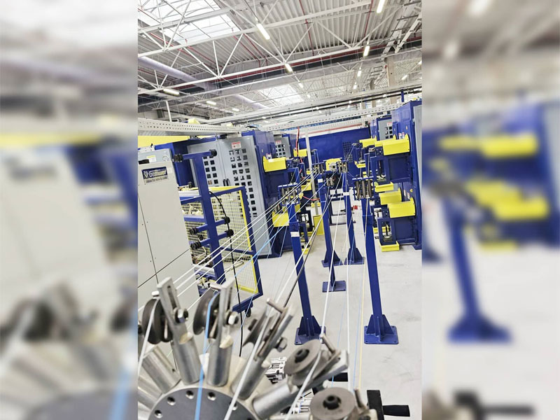
Cable Stranding: Combining Fibers into a Structured Assembly
Individual buffered fibers or loose tubes are assembled into a multi-fiber cable on a stranding machine. This step determines the overall fiber count, mechanical performance, and physical configuration of the finished cable.
In loose-tube designs, multiple tubes — each containing 2 to 24 fibers — are stranded in a helical or SZ (reverse oscillating) pattern around a central strength member, most commonly a glass-reinforced plastic (GRP) rod or aramid yarn bundle. SZ stranding allows each tube to be accessed independently without unwinding the entire cable, a major advantage for field splicing.
Ribbon cable, another common architecture, uses a flat array of 4, 6, 8, or 12 fibers bonded side by side with a matrix material, then stacks multiple ribbons into a central tube or slot core. Ribbon cables can accommodate over 6,000 fibers in a single cable sheath, making them highly efficient for high-density central office deployments and data center trunk cables.
| Construction Type | Fiber Buffer | Fiber Count Range | Typical Application |
|---|---|---|---|
| Tight Buffered | 900 µm over 250 µm | 2–144 | Indoor, premises, plenum |
| Loose Tube | Gel-filled PBT tube | 2–864 | Outside plant, long-haul |
| Ribbon | Matrix-bonded arrays | 72–6,912 | Data center, central office |
| Central Tube (Unitube) | Gel-filled single tube | 2–24 | Access networks, FTTH drops |
The Role of the Wire and Cable Extruder in Jacket Application
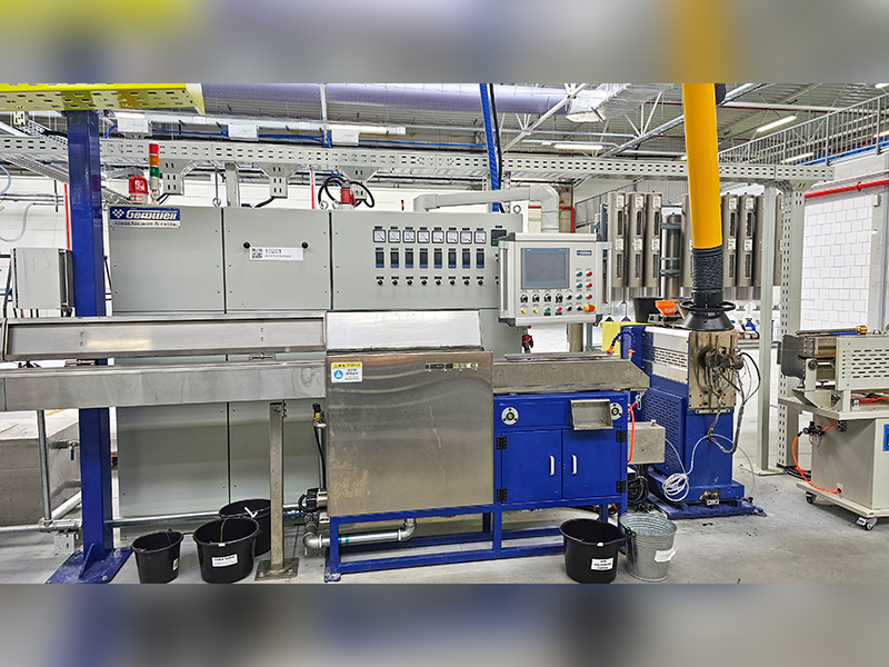
After stranding, the cable core receives its outer jacket — the final protective layer that determines the cable's environmental suitability. This is the most visible application of the wire and cable extruder in the fiber optic manufacturing line, and it directly affects flame retardancy, UV resistance, crush strength, and installation performance.
A wire and cable extruder for this purpose consists of a barrel and screw mechanism that melts thermoplastic compound and forces it through a crosshead die at controlled pressure and temperature. For fiber optic jackets, the extruder must operate with especially fine control because the optical fibers inside cannot tolerate excessive tension or thermal shock during the jacketing pass.
Key Extruder Parameters for Fiber Optic Jacketing
- Screw design: Single-screw extruders with L/D ratios of 20:1 to 30:1 are standard for jacket compounds. Barrier screws improve melt homogeneity, reducing surface defects in the finished jacket.
- Melt temperature: Varies by material — typically 170–200°C for PVC, 230–260°C for HDPE, and 280–310°C for LSZH (Low Smoke Zero Halogen) compounds.
- Line speed: Modern wire and cable extruder systems designed for fiber optic jacketing can run at up to 150–200 m/min for smaller diameter cables.
- Caterpillar haul-off tension: Must be carefully calibrated. Excess tension strains the optical fibers and introduces permanent signal loss.
- Cooling trough length: HDPE and LSZH jackets require longer cooling paths — sometimes 6 to 12 meters — to prevent surface shrinkage and maintain jacket roundness.
LSZH compounds, required by IEC 60332-1 and EN 50200 for use in public buildings and transportation infrastructure, are more challenging to extrude than PVC because of their higher filler content (typically aluminum trihydrate or magnesium hydroxide as flame retardants). A wire and cable extruder handling LSZH must generate sufficient shear to disperse these mineral fillers uniformly without degrading the polymer matrix. Some manufacturers use a twin-screw extruder compounding stage upstream of the crosshead to ensure compound consistency.
Armoring Before the Final Jacket
Many outdoor and direct-burial cables incorporate a metallic or dielectric armor layer between the inner jacket and the outer jacket. Corrugated steel tape (CST) armor provides rodent resistance and crush protection, while aramid yarn or fiberglass provides the same protection in all-dielectric designs. If armor is present, the cable passes through a second jacketing extruder head after armoring — making the wire and cable extruder an even more repeated element across the production line.
Strength Members and Moisture Barriers: What Holds the Cable Together
Optical fibers carry no tensile load themselves — glass simply cannot be stretched without fracturing. All installation tension must be borne by dedicated strength members integrated into the cable design.
- Aramid yarn (Kevlar): The most common strength element in indoor and distribution cables. Typical tensile load ratings range from 100 N for small 2-fiber drop cables to over 2,700 N for indoor trunk cables. Aramid yarn is placed in the interstices between the cable core and the outer jacket.
- Glass-reinforced plastic (GRP) rod: Used as a central strength member in loose-tube outdoor cables. A 5 mm GRP rod provides substantial tensile strength and bend protection while keeping the cable non-conductive and lightning-safe.
- Steel wire or steel tape: Used in aerial self-supporting cables (ADSS cables use no steel) or lashed aerial designs. Some direct-burial cables combine steel armor with water-blocking tapes for dual protection.
- Water-blocking elements: Gel-filled interstices, swellable tapes, or dry water-blocking yarn prevent longitudinal water migration, which can cause hydroxyl contamination of the glass over time, increasing attenuation at the 1383 nm water peak — a known problem in early non-zero water peak (NZWP) fibers.
Types of Optical Fiber: Single-Mode vs. Multimode
The refractive index profile built into the preform determines whether the resulting fiber is single-mode or multimode — a distinction that has profound implications for the cable's application, cost, and performance.
| Parameter | Single-Mode (OS2) | Multimode OM3 | Multimode OM5 |
|---|---|---|---|
| Core diameter | 9 µm | 50 µm | 50 µm |
| Typical attenuation | ≤0.2 dB/km @1550nm | ≤3.0 dB/km @850nm | ≤3.0 dB/km @850nm |
| Max reach (100G) | >80 km with amplification | 100 m | 150 m (SWDM4) |
| Light source | Laser (DFB/external cavity) | VCSEL (850 nm) | VCSEL (850–950 nm) |
| Primary use | Telecom, long-haul, FTTH | Enterprise LAN, data center | Short-reach data center SWDM |
Single-mode fiber has a 9 µm core, which allows only one propagation mode, eliminating modal dispersion entirely and enabling transmission over tens to hundreds of kilometers. Multimode fiber, with its 50 or 62.5 µm core, allows hundreds of modes and is easier to terminate and connect, but modal dispersion limits bandwidth over distance. The graded-index profile of modern OM3/OM4/OM5 fibers — where the refractive index decreases parabolically from center to edge — compensates significantly for modal dispersion, enabling 10G to 400G transmission over shorter enterprise distances.
Quality Testing Throughout the Manufacturing Process
Fiber optic cable manufacturing is governed by multiple international and domestic standards. Quality testing is not a final-stage activity — it is integrated throughout every step of production.
Fiber-Level Tests (Post-Drawing)
- Attenuation: Measured with an OTDR (Optical Time Domain Reflectometer) or cutback method at 1310, 1383, 1550, and 1625 nm for single-mode; at 850 and 1300 nm for multimode.
- Proof test: Each fiber spool is subjected to a tensile proof test — typically 0.5% to 1% elongation — to screen out any fibers with surface flaws. Fibers that fail break during the test and are spliced out.
- Cutoff wavelength: Determines the shortest wavelength at which the fiber operates in true single-mode. Must be below 1260 nm for OS2 compliance.
- Mode field diameter (MFD): Affects splice loss and connector coupling efficiency. ITU-T G.652 specifies 9.2 ± 0.4 µm at 1310 nm.
- Chromatic dispersion and PMD: Critical for high-speed transmission; both must meet the values prescribed by the relevant ITU or IEC fiber standard.
Cable-Level Tests (After Jacketing)
- Crush resistance: Per IEC 60794-1-2 Method E1; a flat force is applied across the cable cross-section to verify the jacket and structure protect fibers without attenuation change.
- Impact test: A weighted drop hammer is used to simulate accidental mechanical blows during installation.
- Temperature cycling: Cables are cycled from −40°C to +70°C (or wider for harsh environments) while optical attenuation is monitored. Changes must remain within defined limits throughout the cycle.
- Water immersion and penetration: Validates gel filling or dry water-blocking effectiveness per IEC 60794-1-2 Method F5.
- Jacket spark test: A high-voltage spark tester runs along the cable jacket to detect pinholes or thin spots introduced during extrusion — a quality control step applied directly on the wire and cable extruder line.
Specialty Fiber Optic Cables: ADSS, Submarine, and Micro-Duct
Beyond the standard loose-tube and tight-buffered designs, several specialty cable constructions require adapted manufacturing approaches and specific extruder configurations.
ADSS (All-Dielectric Self-Supporting) Cables
ADSS cables are designed to be lashed to power line towers without a messenger wire. They must withstand wind, ice loading, and span lengths up to 700 meters without sag. The outer jacket is made from a track-resistant AT compound that resists degradation from high-voltage electric fields induced by proximity to energized conductors. The wire and cable extruder used for ADSS jacketing must handle these specialty AT compounds, which have different rheological behavior than standard HDPE, requiring adjusted screw temperature profiles and pressure settings.
Submarine Fiber Optic Cable
Submarine cables must survive depths exceeding 8,000 meters in transoceanic routes — pressures above 80 MPa. The fiber unit is placed in a copper tube hermetically sealed by welding to prevent hydrogen ingress, which causes fiber attenuation to increase over decades. Layers of high-tensile steel wires and polyethylene jackets are applied in multiple passes, each requiring its own jacketing extruder stage. The manufacturing of a single transoceanic cable segment can involve over a dozen sequential extrusion passes.
Micro-Duct and Blown Fiber Cables
Blown fiber cables are designed to be installed by compressed air through pre-installed micro-ducts, typically 5 to 10 mm in diameter. The cable outer surface must have a very low coefficient of friction — often achieved by co-extruding a slippery nylon or HDPE outer layer with fine surface texture on the wire and cable extruder — to allow air-assisted installation over distances of 1 km or more in a single blow. This approach drastically reduces trenching costs in FTTH rollouts.
From Factory Drum to Installed Network: Final Steps
After all jacketing and testing, the finished fiber optic cable is wound onto wooden or plastic drums in standard shipping lengths. Common reel lengths for loose-tube outdoor cables are 2 km, 4 km, and 6 km. Each drum is labeled with the cable type, fiber count, fiber type (OS2, OM4, etc.), drum length, and the date and shift of production — all traceable to the individual draw tower run and preform batch.
Factory acceptance testing (FAT) at this stage involves OTDR testing of every fiber on every drum to produce a full attenuation trace. This trace is archived and shipped with the cable to serve as a reference against which field-measured OTDRs can be compared after installation, making it easy to identify any damage introduced during pulling or trenching.
Connectorization — attaching factory-polished connectors to fiber ends — is optionally performed at the cable plant or at the installation site. Factory-polished connectors achieve insertion losses below 0.2 dB with return losses above 50 dB for APC (angled physical contact) finishes, performance that is difficult to replicate consistently in field conditions.
Frequently Asked Questions
What raw material is fiber optic cable made from?
The optical fiber itself is made from ultrapure silica glass (silicon dioxide, SiO₂), with dopants like germanium dioxide used to adjust the refractive index. The protective coatings, buffer tubes, and jacket are made from various thermoplastics such as acrylate, PBT, PVC, HDPE, PVDF, or LSZH compounds, all processed through extrusion equipment.
How thin is an optical fiber compared to a human hair?
A single optical fiber after drawing has an outer diameter of 125 micrometers (0.125 mm), which is roughly the diameter of an average human hair. The glass core itself — the part that carries light — is only 9 µm wide in single-mode fiber, about one-tenth the width of a hair.
What does a wire and cable extruder do in fiber optic cable production?
A wire and cable extruder melts thermoplastic compound and applies it as a continuous, precisely dimensioned layer over the optical fiber or cable core. In fiber optic manufacturing, extruders are used at multiple stages: forming tight buffer coatings around individual fibers, producing loose buffer tubes that contain groups of fibers, and applying the cable's outer jacket. The extruder must operate with tight temperature and speed control to avoid damaging the delicate optical fibers inside.
How long does it take to manufacture fiber optic cable?
Preform fabrication takes several days to a week per batch. Fiber drawing at 15–25 m/s means a single 5,000 km fiber spool takes roughly 60–90 hours of continuous drawing tower operation. Secondary processing, stranding, and jacketing add further days. Total cycle time from raw materials to finished drum is typically two to four weeks for a standard outdoor loose-tube cable.
Can fiber optic cable be made with plastic instead of glass?
Yes. Plastic optical fiber (POF) uses PMMA (polymethyl methacrylate) or fluorinated polymer as the core and cladding material. POF has a much larger core (up to 1 mm) and much higher attenuation (around 150–200 dB/km at 650 nm) compared to silica fiber, so it is limited to short runs under 50 meters — typically automotive networks, home A/V systems, and industrial sensor links where ease of termination outweighs the need for low attenuation.
What is LSZH and why does it matter in fiber optic cables?
LSZH stands for Low Smoke Zero Halogen. It describes jacket materials that, when exposed to fire, produce minimal smoke and no halogen gases (such as chlorine from PVC). This matters in enclosed spaces like transit tunnels, hospitals, and office buildings where toxic smoke from burning cables poses a serious evacuation hazard. LSZH jackets are applied using a wire and cable extruder configured for higher-viscosity, filler-loaded compounds, and the cables must pass IEC 60332-3, IEC 61034, and IEC 60754 test series.


