 E-mail: info@gem-cablesolution.com
 Address: No.8 Yuefeng Rd, High Tech Zone, Dongtai, Jiangsu, China | No.109 Qilin East Rd, Daning, Humen, Dongguan, Guangdong, China.
 English
  English
 русский
 日本語
日本語 Español
 عربى
عربى 中文简体
中文简体
Content
- 1 How Fiber Optic Cable Is Made: The Short Answer
- 2 Raw Materials: What Fiber Optic Cable Is Actually Made From
- 3 Stage One: Manufacturing the Glass Preform
- 4 Stage Two: Drawing the Fiber on a Drawing Tower
- 5 Stage Three: Coloring, Buffering, and Stranding Fibers
- 6 Stage Four: Jacketing With a Wire and Cable Extruder
- 7 Critical Equipment on a Fiber Optic Cable Jacketing Line
- 8 Fiber Optic Cable Types and Their Different Manufacturing Approaches
- 9 Quality Testing Throughout the Manufacturing Process
- 10 Key Factors That Affect Fiber Optic Cable Performance and Longevity
- 11 Starting a Fiber Optic Cable Production Line: Practical Considerations
- 12 Fiber Optic Cable Standards and Compliance Requirements
How Fiber Optic Cable Is Made: The Short Answer
Fiber optic cable is made by drawing ultra-pure silica glass into hair-thin strands called optical fibers, coating them with protective polymer layers, bundling them into a core assembly, and finally extruding an outer jacket around the entire structure using a wire and cable extruder. The result is a cable capable of transmitting data at the speed of light over distances of tens of kilometers with virtually no signal loss.
The full manufacturing process spans multiple highly controlled stages — from chemical vapor deposition of silica preforms, to fiber drawing towers operating at over 2,000°C, to jacketing lines where a wire and cable extruder applies polymer coatings at speeds exceeding 1,000 meters per minute. Each stage demands precision equipment, tight tolerances, and rigorous quality control.

Raw Materials: What Fiber Optic Cable Is Actually Made From
The optical fiber at the heart of every cable starts with silicon tetrachloride (SiCl₄) or silicon dioxide (SiO₂) of extraordinary purity — typically 99.9999% or better. Even a single metallic impurity at the parts-per-billion level can scatter light and reduce transmission quality. Alongside the silica, dopants such as germanium dioxide (GeO₂) are added to the core to raise its refractive index slightly above that of the cladding, creating the total internal reflection that keeps light trapped inside the fiber.
Beyond glass, a finished cable contains several other material categories:
- Primary coating: A soft UV-curable acrylate applied directly over the glass to cushion microbends and protect the surface from moisture.
- Secondary coating: A harder acrylate layer that gives the fiber mechanical strength and abrasion resistance.
- Buffer tubes or tight buffer: Loose-tube designs use gel-filled PBT (polybutylene terephthalate) tubes; tight-buffered designs use nylon or PVDF extruded directly over the fiber.
- Strength members: Aramid yarn (Kevlar), glass-reinforced plastic (GRP) rods, or steel wire depending on cable type and application.
- Outer jacket: Low-smoke zero-halogen (LSZH) polyethylene, PVC, or polyurethane, applied by a wire and cable extruder and chosen based on installation environment.
The specific combination of these materials determines whether the finished product is an indoor patch cable, a direct-burial outdoor cable, an armored submarine cable, or a flame-retardant riser cable.
Stage One: Manufacturing the Glass Preform
Everything begins with the preform — a solid glass rod, typically 1–1.5 meters long and 50–150 mm in diameter, whose cross-sectional profile is an exact scaled-up replica of the finished fiber. The ratio between core diameter and cladding diameter in the preform is preserved faithfully during drawing, so every dimensional decision made at this stage propagates all the way to the final product.
Modified Chemical Vapor Deposition (MCVD)
In the MCVD process, a rotating silica tube is mounted in a glass-working lathe. Gaseous precursors — SiCl₄, GeCl₄, POCl₃, and oxygen — are fed into one end while a hydrogen-oxygen torch traverses the outside. The gases react at around 1,600°C, depositing soot particles on the tube's inner wall. Each pass of the torch deposits one layer of glass with a slightly different composition, building up the graded-index core layer by layer. After hundreds of passes, the tube is collapsed into a solid preform rod under high temperature.
Outside Vapor Deposition (OVD) and Vapor Axial Deposition (VAD)
OVD and VAD are the dominant methods used by large-scale producers like Corning and Fujikura. In OVD, a rotating mandrel traverses through a flame hydrolysis burner; SiCl₄ and GeCl₄ react with hydrogen and oxygen to deposit silica soot on the outside of the mandrel. After deposition, the mandrel is removed and the porous soot blank is sintered in a furnace with a chlorine atmosphere to drive out OH⁻ ions (which cause water peak attenuation), then consolidated into a bubble-free glass preform. VAD deposits soot axially on the end of a rotating seed rod, growing the preform continuously — a format that suits high-volume production because it produces very long preforms without interruption. A single large OVD or VAD preform can yield over 3,000 km of finished fiber.
Stage Two: Drawing the Fiber on a Drawing Tower
The fiber drawing tower is one of the most striking pieces of equipment in any optical fiber plant. Typically standing 10–20 meters tall, it feeds the preform vertically into a graphite resistance furnace or zirconia induction furnace where the tip is heated to approximately 2,000–2,200°C. At this temperature, the glass softens and a thin strand — called a fiber "neck-down" — falls under gravity and is captured by a capstan at the base of the tower.
The capstan controls draw speed, which is the primary variable used to regulate fiber diameter. Modern drawing towers operate at speeds of 1,500–2,500 meters per minute, and a laser micrometer stationed just below the furnace measures the fiber diameter continuously — typically maintaining it within ±0.1 µm of the target 125 µm cladding diameter. If the diameter drifts, the control system adjusts draw speed in real time within milliseconds.
Inline Coating Application
Immediately after the diameter measurement point, the bare glass fiber passes through a dual coating die where liquid UV-curable acrylate is applied in two concentric layers simultaneously — the soft primary coat at roughly 190–200 µm outer diameter, and the harder secondary coat bringing the total to about 245–250 µm. The coated fiber then passes through UV lamps that cure both layers within fractions of a second. This inline coating step is critical: bare silica glass has very high tensile strength (up to 700 kpsi) but is extremely sensitive to surface damage from atmospheric moisture and handling. The polymer coating protects that surface from the moment the glass solidifies.
The coated fiber is wound onto reels that hold anywhere from 25 km to over 100 km of fiber, depending on reel size and fiber type. Each reel is then subjected to proof testing, where the fiber is pulled through a capstan system that applies a controlled tensile load — typically 100 kpsi — to verify that no weak points exist along the entire length.
Stage Three: Coloring, Buffering, and Stranding Fibers
After proof testing, individual fibers are color-coded using a UV ink coloring line, which applies a thin layer of pigmented UV-curable ink to the secondary coating surface. The standard color sequence follows TIA-598 (or IEC 60304 internationally): blue, orange, green, brown, slate, white, red, black, yellow, violet, rose, aqua — repeated for each group of 12 fibers in high-count cables. This color coding is the only way to identify individual fibers in cables containing 96, 144, 288, or even 3,456 fibers.
Loose Tube vs. Tight Buffer Construction
The next major process choice is how fibers are packaged inside the cable structure. In loose tube construction, groups of 6–12 fibers are placed inside small PBT or PP tubes with an inner diameter 1.5–3× the fiber bundle diameter. The excess fiber length (EFL) inside the tube — typically 0.2–0.5% more fiber length than tube length — allows the fibers to flex without strain as the cable expands or contracts with temperature. Gel-filled loose tubes provide additional moisture and hydrogen blocking. This construction dominates outdoor OSP (outside plant) cables.
In tight buffer construction, a thermoplastic material — typically nylon 12 or PVDF — is extruded directly over each coated fiber, bringing the fiber package to 900 µm. A wire and cable extruder with a precision crosshead die performs this operation, maintaining the concentricity of the buffer layer to within ±25 µm. Tight-buffered fibers are easier to terminate, making this construction standard for indoor distribution and premise cables.
Once individual fibers or loose tubes are prepared, they are stranded together around a central strength member using a planetary or SZ stranding machine. SZ stranding — where the lay direction reverses periodically — is preferred because it allows mid-span access without unwinding the entire cable.
| Feature | Loose Tube | Tight Buffer |
|---|---|---|
| Typical application | Outdoor OSP, aerial, direct burial | Indoor, riser, distribution |
| Fiber count range | Up to 3,456+ fibers | Typically 2–144 fibers |
| Temperature range | –40°C to +70°C | –20°C to +60°C (typical) |
| Moisture protection | Excellent (gel or dry water-blocking) | Moderate (relies on jacket) |
| Termination ease | Requires gel cleaning | Fast, clean |
| Buffer extrusion equipment | Tube extruder (larger die) | Precision wire and cable extruder |
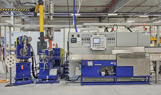
Stage Four: Jacketing With a Wire and Cable Extruder
Jacketing is the final major manufacturing stage and the one where wire and cable extruder technology plays its most visible role. The stranded cable core — with its central strength member, buffer tubes or tight-buffered fibers, water-blocking tape or yarn, and any armoring — passes through an extrusion crosshead where molten thermoplastic is applied uniformly around the entire circumference.
How the Extruder Works
A wire and cable extruder for fiber optic jacketing is fundamentally a single-screw or twin-screw plasticating machine. The screw, rotating inside a heated barrel, melts and homogenizes the polymer pellets fed from a hopper. The screw geometry — including the compression ratio, metering zone length, and L/D ratio (typically 24:1 to 30:1 for jacket applications) — is matched to the specific polymer being processed. Different jacket materials require significantly different processing conditions:
- HDPE (High-Density Polyethylene): Processing temperature 180–230°C; excellent moisture and UV resistance; used in aerial and direct-burial cables.
- LSZH (Low-Smoke Zero-Halogen): Processing temperature 170–210°C; mandatory in tunnels, data centers, and public buildings; requires careful screw design because LSZH compounds are often more viscous and thermally sensitive than PE.
- PVC: Processing temperature 160–190°C; low cost, flexible, flame-retardant; commonly used for indoor cables.
- Polyurethane (TPU): Processing temperature 190–220°C; outstanding abrasion resistance and flexibility in cold temperatures; used in industrial and military applications.
- Nylon (PA12): Processing temperature 220–250°C; high chemical resistance; used where fuel or oil exposure is possible.
The crosshead die assembly at the end of the extruder barrel positions a tip (or guider tube, in pressure tooling configurations) that the cable core passes through, surrounded by the die land through which molten polymer flows and is shaped onto the cable. Jacket wall thickness is controlled by the balance between line speed and extruder output (in kg/hr), and modern lines use closed-loop diameter measurement — laser gauges or X-ray thickness gauges — feeding back to the extruder drive and haul-off capstan to maintain specifications within ±0.1 mm or tighter.
Cooling and Caterpillar Haul-Off
Immediately after the crosshead, the jacketed cable enters a water trough — typically 8–15 meters long — where it is quenched. The cooling rate affects the crystallinity of semi-crystalline polymers like HDPE and directly influences the jacket's mechanical properties. For very high line speeds (above 200 m/min), forced water spray or vacuum-assisted cooling troughs maintain adequate heat removal. A caterpillar haul-off (belt-type tractor unit) grips the cable gently to maintain tension and line speed without crushing the sensitive optical structure inside.
Dual-Layer Jacketing and Armored Cables
Many outdoor or armored cables require two wire and cable extruder passes. In the first pass, an inner jacket (often PE) is applied over the stranded core. The cable then passes through a corrugated steel tape (CST) armouring unit or interlocked aluminum armor station before entering a second extruder that applies the outer jacket. This tandem extruder line may span 50–80 meters in total length and is capable of producing finished armored fiber optic cable at rates of 30–80 m/min.
For submarine cables, the process is even more involved: up to six layers of wire armoring (individual steel wires applied by planetary stranding machines) may be added, with each wire layer requiring its own bedding compound extrusion pass between it and the next wire layer.
Critical Equipment on a Fiber Optic Cable Jacketing Line
A complete fiber optic cable jacketing line integrates many machines working in coordinated sequence. Understanding what each does helps clarify why the wire and cable extruder and its peripheral equipment are so central to cable quality.
- Pay-off stand: Holds the cable core reel and pays off the core at controlled tension — too much tension can stress fibers inside; too little causes sag and diameter variation.
- Preheater: Dries and warms the cable core surface before it enters the extruder crosshead, improving adhesion between the jacket and the cable core.
- Single-screw wire and cable extruder: The core processing machine, with barrel zones individually temperature-controlled in 5–7 sections, a gearbox driving the screw at 10–120 RPM, and a melt pressure sensor at the die head for process monitoring.
- Crosshead die: Precision-machined steel assembly that aligns the cable core with the polymer flow. Die concentricity — how precisely the jacket is centered on the cable — directly determines mechanical performance and electrical properties.
- Laser diameter gauge: Non-contact measurement at 2,000+ scans/second, detecting diameter changes in real time and sending correction signals to haul-off speed control.
- Water trough with temperature zones: Precise quench control for crystallinity management; often two zones — a hot zone to prevent surface sink marks, then a cold zone for rapid solidification.
- Caterpillar haul-off: Dual-belt or four-belt design with pneumatic pressure control to avoid crushing; drives overall line speed and backpressure against the extruder.
- Spark tester (for copper hybrid cables): Applies high voltage to detect pinholes in the jacket; not required for all-dielectric fiber cables but used in armored cables where the jacket must be electrically isolating.
- Take-up with traverse winding: Winds finished cable onto shipping reels or drums with precise traverse control to prevent reel damage or fiber microbending from uneven spooling pressure.
Among all these components, the wire and cable extruder is the item that cable manufacturers most frequently specify and upgrade, because screw and barrel wear directly degrades melt quality, output consistency, and jacketing uniformity over time. Reputable extruder manufacturers publish screw wear limits — typically allowing no more than 5% reduction in channel depth before replacement — and many cable producers schedule barrel/screw rebuilds every 3–5 years depending on material abrasiveness.
Fiber Optic Cable Types and Their Different Manufacturing Approaches
Not all fiber optic cables are made the same way. The end-use environment drives substantial differences in which manufacturing steps are included, what materials flow through the wire and cable extruder, and how tightly tolerances are held.
Single-Mode vs. Multimode Fiber Cables
Single-mode fiber (SMF) has a core diameter of just 8–10 µm — roughly one-tenth the width of a human hair — and a cladding of 125 µm. Manufacturing SMF requires tighter control of core-to-cladding concentricity (typically ≤0.5 µm offset) and core circularity during preform fabrication and drawing. Multimode fiber (MMF) comes in OM1 through OM5 categories with core diameters of 50 or 62.5 µm; the graded-index profile of OM3/OM4/OM5 fiber requires very precise compositional control of the GeO₂ dopant gradient during preform deposition. The cable construction around both fiber types can be identical; it is the fiber itself where the key differences lie.
Ribbon Cable Manufacturing
High-density ribbon fiber optic cable — used extensively in data center interconnects and central office applications — bonds 4, 8, or 12 individual colored fibers side-by-side in a flat matrix using UV-curable ribbon matrix material. The ribboning machine precisely spaces and tensions each fiber as they enter a flat die where matrix material is applied and UV-cured. Multiple ribbons are then stacked and placed inside a slotted-core or central-tube cable structure. A 288-fiber ribbon cable can be less than 12 mm in outer diameter, compared to 18–22 mm for a comparable stranded loose-tube design. The jacketing step for ribbon cables uses the same wire and cable extruder technology as conventional cables, but the core assembly is notably stiffer and requires higher tension monitoring on the pay-off stand.
Bend-Insensitive Fiber (BIF) Cables
Bend-insensitive fiber, standardized as ITU-T G.657, incorporates a trench-assisted or nanostructured cladding design that dramatically reduces macrobend losses. Cables built with BIF — particularly G.657.A2 and G.657.B3 grades — can tolerate bends down to 5 mm radius with less than 0.1 dB added loss at 1,550 nm. These cables are common in FTTH (fiber to the home) drop cables, which are routed through conduit bends, around doorframes, and through tight interior runs. The BIF preform fabrication adds complexity (additional cladding layers with different refractive indices), but the subsequent cable manufacturing process — including extruder jacketing — is essentially the same as for standard SMF cables.
Quality Testing Throughout the Manufacturing Process
Quality control in fiber optic cable manufacturing is not a final-step inspection — it is woven into every stage of production. Skipping or weakening any of these checks produces cables that may pass initial tests but fail prematurely in the field, where repair costs dwarf the original cable purchase price.
Fiber-Level Testing
Every fiber reel leaving the drawing tower is tested for:
- Attenuation: Measured with an OTDR (optical time-domain reflectometer) at both 1,310 nm and 1,550 nm. Standard SMF must be ≤0.35 dB/km at 1,310 nm and ≤0.20 dB/km at 1,550 nm per ITU-T G.652.D.
- PMD (polarization mode dispersion): Critical for high-speed coherent transmission systems; specified as a link design value (e.g., ≤0.20 ps/√km for G.652.D).
- Geometry: Mode field diameter, cladding diameter, core-cladding concentricity, and cladding non-circularity — all measured by automated video inspection systems at the drawing tower.
- Proof test: 100 kpsi minimum tensile load applied along the full reel length to screen out any weak sections.
Cable-Level Testing
After jacketing, the finished cable reel undergoes a comprehensive suite of tests defined by IEC 60794-1 and relevant IEC 60794-x series standards, or ANSI/ICEA equivalents for the North American market:
- Tensile load: Cable is pulled to rated installation load and then to proof load; attenuation increase must remain below 0.1 dB during loading and return to baseline after release.
- Crush resistance: A flat plate applies rated crush force (e.g., 2,200 N/100 mm for typical OSP cables); attenuation is monitored in real time via a launched light source and power meter.
- Bend test: Cable is cycled around a mandrel of specified diameter; for standard OSP cables this is 20× the cable outer diameter.
- Temperature cycling: Cable reels are tested from –40°C to +70°C (or wider ranges for specialty cables); attenuation is measured at low and high temperature extremes.
- Water penetration: A 1-meter section of cable is subjected to 1 m hydraulic head for 24 hours; water must not penetrate beyond the test section ends.
- Jacket thickness and OD: Cross-sections cut from the cable ends are measured under a calibrated optical microscope to verify jacket wall uniformity — a direct indicator of extruder process control.
Some customers specify 100% OTDR measurement of every fiber in every reel before shipping — a practice common in telecom carrier procurement. This end-to-end OTDR trace also creates a baseline record that can be used years later when diagnosing field faults.
Key Factors That Affect Fiber Optic Cable Performance and Longevity
Understanding what happens inside the manufacturing process explains why certain cables outperform others in the field and why the right extruder setup — material selection, temperature profile, screw design — is inseparable from the cable's long-term reliability.
Hydrogen Darkening
Hydrogen generated by the electrolytic corrosion of steel wire armor, or by the degradation of gel compounds and polymer coatings, can diffuse into the glass fiber and react with defects in the silica lattice to form Si-OH (silanol) bonds that absorb infrared light — a phenomenon called hydrogen darkening. The primary manufacturing defense is rigorous elimination of water from all gel and polymer systems (this is why water-blocked tubes and quality gel formulations are specified at sub-10 ppm water content), and the use of carbon or hermetic coatings on the fiber itself in the most demanding environments. The wire and cable extruder can contribute to or mitigate this risk: properly dried polymer granules and well-controlled melt temperatures minimize moisture entrainment into the jacket structure.
Microbending and Macrobending
Microbending refers to microscopic lateral deformations of the fiber caused by non-uniform radial pressure from buffer tube walls, wrapping tape edges, or irregular jacket surfaces. Even deformations in the nanometer range increase attenuation measurably at 1,550 nm. A wire and cable extruder producing a jacket with surface ripple (a melt fracture defect common when melt temperature is too low or draw speed too high relative to extruder output) can introduce patterned lateral forces on the cable core and cause microbend losses that would not appear in a benign lab test but manifest under thermal contraction in the field. Macrobending — wrapping the cable around too tight a radius — is an installation issue, but cables with lower bending stiffness (thinner jacketing walls, fewer strength members) are more vulnerable, making jacket design another intersection point between extruder-applied materials and optical performance.
UV Degradation of Outdoor Jacket Materials
Aerial fiber optic cables must withstand decades of UV exposure without jacket cracking or embrittlement. Carbon black at 2–3% by weight in HDPE provides effective UV shielding and is the industry standard for direct-burial and aerial cables. Cables intended for indoor use may use other stabilizer packages, but the formulation is typically supplied as a pre-compounded pellet to the cable manufacturer, who feeds it directly into the wire and cable extruder. The extruder's processing conditions must be compatible with the stabilizer system — excessive screw shear or barrel temperature can degrade antioxidants that are essential for long-term thermal stability, even in cables never exposed to sunlight.
Starting a Fiber Optic Cable Production Line: Practical Considerations
For a manufacturer looking to enter fiber optic cable production — or to expand from copper cable into fiber — the equipment investment and process knowledge required are substantial but well-defined. The drawing tower and preform production equipment represent the highest barriers to entry (and are typically not justified unless producing fiber at multi-million kilometer scales annually). Most cable manufacturers purchase fiber from established fiber producers — Corning, Prysmian, Fujikura, Sumitomo, YOFC — and focus their capital on cable design and jacketing line equipment.
Selecting a Wire and Cable Extruder for Fiber Optic Jacketing
The most critical equipment decision for a fiber optic cable jacketing line is the wire and cable extruder selection. Key parameters to evaluate include:
- Screw diameter: For fiber optic jacket applications, 45 mm to 90 mm screw diameters are typical. Smaller screws (45–60 mm) give better output consistency and material response at the lower throughput rates needed for small-diameter cables; larger screws suit high-output jacketing of large-count OSP cables.
- L/D ratio: A minimum of 24:1 is recommended for fiber optic jacket materials. LSZH compounds especially benefit from 28:1 or 30:1 L/D ratios that allow longer melting and mixing zones.
- Drive system: AC servo or vector-controlled drives offer the speed stability (±0.1%) needed to maintain jacket wall consistency at variable line speeds. DC drives are being phased out of new installations.
- Temperature control zones: A minimum of 5 independently controlled barrel zones plus crosshead zone. PID controllers with better than ±1°C stability are standard on modern cable extruder systems.
- Instrumentation: Melt pressure transducer at the die head, melt temperature probe at the screw tip, and an optical or X-ray diameter gauge downstream — all feeding into a line control PLC with data logging for production traceability.
- Material handling: A gravimetric or volumetric blending and dosing unit for masterbatch addition upstream of the extruder hopper, with a desiccant dryer for moisture-sensitive materials like nylon and TPU.
A well-specified fiber optic jacketing line built around a suitable wire and cable extruder can pay back its capital cost within 18–36 months in markets with strong fiber deployment demand, provided that process recipes, operator training, and quality systems are established before production ramp-up.
Difference Between Fiber Optic and Copper Cable Extruder Requirements
Manufacturers already running copper wire and cable extruder lines often ask whether the same equipment can be used for fiber optic jacketing. The answer is: sometimes, with modifications. Fiber optic cables require much more precise tension control on the pay-off (to avoid stressing the fibers inside), and the crosshead die alignment is more critical because there is no electrical test (like continuity or capacitance) that catches die misalignment — the jacket wall variation shows up only in mechanical tests or post-installation failures. Additionally, if the existing extruder has been used for PVC processing, it must be thoroughly purged before running LSZH or PE compounds to prevent contamination. Dedicated extruder lines for fiber optic jacketing — not shared with copper cable production — are strongly preferred in quality-conscious operations.
Fiber Optic Cable Standards and Compliance Requirements
Fiber optic cables sold into telecom, data center, industrial, and military markets must comply with a complex web of international and regional standards. Compliance is not optional — major network operators and procurement bodies require third-party type-approval test reports before placing orders, and some standards (like LSZH flame performance in EU public buildings) are legally mandated.
| Standard | Scope | Region |
|---|---|---|
| ITU-T G.652 | Standard SMF characteristics | Global |
| ITU-T G.657 | Bend-insensitive SMF for FTTH | Global |
| IEC 60794-1 | Optical fibre cable test methods | Global / EU |
| IEC 60794-3 | Outdoor optical fibre cables | Global / EU |
| ANSI/ICEA S-87-640 | Optical fiber outside plant cable | North America |
| TIA-568.3-D | Optical fiber cabling component standard | North America |
| EN 50399 / IEC 60332 | Flame propagation and smoke for cables | EU (CPR) |
| MIL-PRF-85045 | Fiber optic cable for military use | USA (Defense) |
The EU Construction Products Regulation (CPR) deserves special mention because it directly governs the jacket material choices and therefore extruder process requirements for cables installed in European buildings. Under CPR, cables must be classified from Eca (minimum performance) through B2ca, B1ca, and Aca (highest performance). Achieving B1ca or Aca classification requires LSZH compounds with extremely low heat release and smoke production rates — compounds that place demanding requirements on the wire and cable extruder in terms of melt temperature uniformity, residence time control, and die pressure stability.


