E-mail: info@gem-cablesolution.com
 Address: No.8 Yuefeng Rd, High Tech Zone, Dongtai, Jiangsu, China | No.109 Qilin East Rd, Daning, Humen, Dongguan, Guangdong, China.
 English
  English
 русский
 日本語
日本語 Español
 عربى
عربى 中文简体
中文简体
Content
- 1 The Direct Answer: How to Calculate Wire Cable Size
- 2 Understanding Wire and Cable Sizing Systems: AWG vs. mm²
- 3 Step-by-Step Method to Calculate Wire Cable Size
- 4 The Role of Insulation Type in Cable Ampacity
- 5 Copper vs. Aluminum Conductors: Sizing Differences
- 6 Cable Sizing for Motor Circuits
- 7 Voltage Drop Calculation Deep Dive: Long Cable Runs
- 8 How Cable Construction Quality Affects Sizing Calculations
- 9 Practical Wire Cable Size Examples by Application
- 10 Short-Circuit and Fault Current Considerations in Cable Sizing
- 11 Common Mistakes in Wire Cable Size Calculation
- 12 Quick Reference: Cable Size Selection Summary
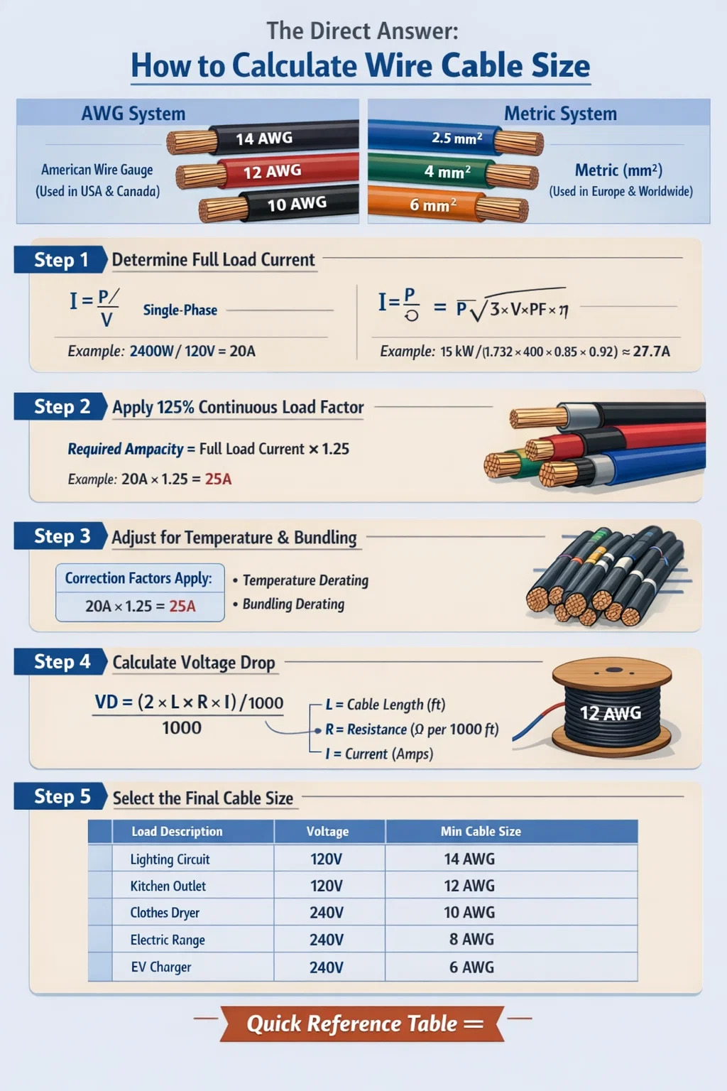
The Direct Answer: How to Calculate Wire Cable Size
To calculate wire cable size, you need to determine the maximum current (ampacity) the cable must carry, then apply voltage drop limits and safety factors to select the correct conductor cross-section. The most widely used formula is based on Ohm's Law combined with the National Electrical Code (NEC) or IEC standards. For most AC systems, the basic rule is: select a conductor where the current-carrying capacity exceeds 125% of the continuous load current. For DC circuits or longer cable runs, voltage drop calculations take priority.
In practical terms, if you have a 20A continuous load on a 120V AC circuit, you multiply 20A × 1.25 = 25A minimum ampacity, which points to a 12 AWG copper conductor under standard NEC ampacity tables. For voltage-sensitive equipment over long distances, voltage drop must be calculated separately using the formula: VD = (2 × L × R × I) / 1000, where L is one-way cable length in feet, R is resistance per 1,000 feet, and I is the load current in amps.
This guide walks through each step of the calculation process, covering both AWG and metric (mm²) systems, different insulation types, installation conditions, and how the quality of cable construction — including how a wire and cable extruder processes the insulation layer — affects the final electrical performance and safety rating of the cable.
Understanding Wire and Cable Sizing Systems: AWG vs. mm²
Before calculating, you need to understand which measurement system applies to your region and application. The two dominant standards are the American Wire Gauge (AWG) system and the metric cross-sectional area system measured in square millimeters (mm²).
American Wire Gauge (AWG) System
AWG is predominantly used in the United States and Canada. Counterintuitively, a lower AWG number means a thicker, higher-capacity conductor. For example, 4 AWG copper carries significantly more current than 14 AWG. The AWG scale runs from 0000 (4/0) at the large end down to 40 AWG for fine wire applications. Common residential and commercial wiring uses 14 AWG, 12 AWG, and 10 AWG for branch circuits, while feeder conductors may use 6 AWG, 4 AWG, 2 AWG, or larger.
Metric Cross-Section System (mm²)
Used throughout Europe, Asia, Australia, and most other parts of the world following IEC standards, the mm² system directly describes the cross-sectional area of the conductor. Common sizes include 1.5 mm², 2.5 mm², 4 mm², 6 mm², 10 mm², 16 mm², 25 mm², 35 mm², 50 mm², and beyond. A 2.5 mm² conductor is roughly equivalent to 14 AWG in terms of cross-section, though exact ampacity depends on insulation type and installation method.
| AWG Size | Approx. mm² | Copper Ampacity (75°C) | Typical Application |
|---|---|---|---|
| 14 AWG | 2.08 mm² | 20A | Lighting circuits |
| 12 AWG | 3.31 mm² | 25A | General outlets |
| 10 AWG | 5.26 mm² | 35A | Air conditioners, dryers |
| 8 AWG | 8.37 mm² | 50A | Electric ranges, EV chargers |
| 6 AWG | 13.3 mm² | 65A | Sub-panels, large motors |
| 4 AWG | 21.2 mm² | 85A | Service entrance feeders |
| 2 AWG | 33.6 mm² | 115A | Main panel feeds |
Step-by-Step Method to Calculate Wire Cable Size
Proper cable sizing follows a logical sequence. Skipping steps leads to either undersized cables that overheat and create fire hazards, or oversized cables that waste material and increase installation cost unnecessarily.
Step 1: Determine the Full Load Current
The starting point for every cable sizing calculation is identifying the full load current (FLC) of the connected equipment. For resistive loads like heaters, this is straightforward: use P = V × I, rearranged to I = P / V. For a 2,400W space heater on a 120V circuit, I = 2,400 / 120 = 20 amps.
For three-phase motor loads, the formula is: I = P / (√3 × V × PF × η), where PF is the power factor and η is efficiency. A 15kW motor at 400V with PF = 0.85 and η = 0.92 results in I = 15,000 / (1.732 × 400 × 0.85 × 0.92) ≈ 27.7A. Always use nameplate data when available rather than calculated estimates.
Step 2: Apply the Continuous Load Multiplier
For loads that operate continuously for 3 hours or more, NEC Section 210.19 requires sizing the conductor at 125% of the continuous load current. If your load draws 20A continuously, the minimum conductor ampacity must be 20 × 1.25 = 25A. This thermal safety margin accounts for heat buildup in the insulation over sustained operation. IEC standards use a similar approach through correction factors applied to base ampacity values.
Step 3: Apply Correction Factors for Temperature and Bundling
Cables installed in high-temperature environments or grouped with other cables must be derated. NEC Table 310.15(B)(1) provides temperature correction factors. At an ambient temperature of 40°C instead of the standard 30°C baseline, a 75°C-rated conductor must be derated by a factor of 0.88. That means a conductor rated 25A at 30°C only carries 22A safely at 40°C ambient.
Bundling correction is equally important. When 4–6 current-carrying conductors share a conduit, apply a 0.80 factor. For 7–9 conductors, use 0.70. For 10–20 conductors bundled together, the factor drops to 0.50. Failure to apply bundling factors is one of the most common causes of overheating in commercial cable trays.
Step 4: Calculate Voltage Drop
Voltage drop limits are typically 3% for branch circuits and 5% total for feeder plus branch circuit combined (per NEC recommendation, though not a hard code requirement for all cases). Use this formula for single-phase AC and DC circuits:
VD (volts) = (2 × L × R × I) / 1000
Where L = one-way cable length in feet, R = resistance in ohms per 1,000 feet (from conductor resistance tables), and I = load current in amps. The factor of 2 accounts for both the outgoing and return conductors.
Example: A 120V circuit, 100 feet one-way, carrying 15A through 14 AWG copper (R = 3.14 Ω/1,000 ft): VD = (2 × 100 × 3.14 × 15) / 1,000 = 9.42 volts, which is 7.85% — well above the 3% limit. Upgrading to 10 AWG (R = 1.24 Ω/1,000 ft) reduces this to 3.72V, or 3.1%, which is marginal but acceptable for non-sensitive loads. For precision equipment, moving to 8 AWG would bring it to 1.8%.
For three-phase systems, the formula modifies to: VD = (√3 × L × R × I) / 1000, replacing the factor of 2 with 1.732 since the phase geometry reduces the effective loop resistance.
Step 5: Select the Final Cable Size
After calculating the required ampacity (with all correction factors applied) and the minimum conductor size needed to meet voltage drop limits, select whichever size is larger. This is the governing cable size. Always round up to the next available standard conductor size — never round down.
The Role of Insulation Type in Cable Ampacity
The insulation material surrounding the conductor directly determines how much heat the cable can safely sustain, which in turn sets the ampacity rating. This is where the manufacturing process — specifically the performance of the wire and cable extruder — has a direct impact on the electrical and thermal properties of the finished product.
Common insulation temperature ratings and their NEC designations include:
- 60°C (140°F) — Type TW, used in older residential wiring. Lower ampacity, not suitable for high-load circuits.
- 75°C (167°F) — Types THW, THWN. Most common commercial and industrial insulation. This is the standard column used in NEC Table 310.15 for conductor sizing in most new installations.
- 90°C (194°F) — Types THHN, XHHW-2, RHH. Higher base ampacity, but NEC often limits termination to 75°C unless equipment is specifically rated for 90°C terminations. Can be used at full 90°C rating in free air or when termination equipment is rated accordingly.
- 150°C and above — Specialty cables using silicone rubber, PTFE (Teflon), or mineral insulation (MI cable). Used in furnaces, industrial ovens, and high-temperature process equipment.
The consistency of insulation thickness is critical. A wire and cable extruder in a modern manufacturing line uses precision die geometry, melt temperature control, and line speed regulation to maintain uniform wall thickness around the conductor. Inconsistent insulation — thinner in some spots — creates localized hot points that reduce effective thermal rating even if the average thickness meets specification. Advanced extruder machinery from manufacturers in China, Europe, and North America now uses laser measurement systems and automatic eccentricity correction to achieve wall thickness tolerances within ±5% or tighter.
| Insulation Type | Temp Rating | 12 AWG Cu Ampacity | Wet/Dry Location |
|---|---|---|---|
| TW | 60°C | 20A | Wet/Dry |
| THW / THWN | 75°C | 25A | Wet/Dry |
| THHN / XHHW-2 | 90°C | 30A | Dry only (THHN) / Wet (XHHW-2) |
| MI Cable | 250°C | 40A+ | Wet/Dry/High heat |
Copper vs. Aluminum Conductors: Sizing Differences
Aluminum conductors are commonly used for service entrance cables, feeders, and utility distribution. They are lighter and less expensive than copper, but aluminum has only about 61% of the conductivity of copper, meaning you need a larger cross-section to carry the same current.
As a practical rule: to match the ampacity of a copper conductor, aluminum requires approximately two AWG sizes larger. Where 6 AWG copper carries 65A (at 75°C), you would need 4 AWG aluminum to carry the same current. For metric sizing, a 16 mm² aluminum conductor roughly matches a 10 mm² copper conductor.
Aluminum also expands and contracts more than copper with temperature cycles, which can cause connection loosening over time. All aluminum conductor terminations must use connectors rated AL/CU, and anti-oxidant compound is required at joints and terminations to prevent oxidation buildup that increases resistance. These are code requirements in most jurisdictions, not optional practices.
From a manufacturing standpoint, the extrusion of insulation over aluminum conductors requires careful control of the line speed and compound temperature in the wire and cable extruder. Aluminum's surface chemistry differs from copper, and some insulation compounds adhere differently. Quality cable manufacturers run adhesion tests to ensure the insulation bonds properly and does not separate from the conductor during flexing or thermal cycling.
Cable Sizing for Motor Circuits
Motor circuits follow different rules than general branch circuits because motors draw very high inrush current at startup — typically 6 to 8 times the full load current for 0.5 to 2 seconds. The cable itself does not need to be sized for this inrush current (the overcurrent protection handles that), but the conductor must be sized based on NEC Article 430 rules rather than standard ampacity tables.
For a single motor, NEC 430.22 requires the branch circuit conductor to be sized at at least 125% of the motor's full load current (FLC) as listed in NEC Tables 430.247–430.250 (not the nameplate value, unless the nameplate is lower than the table value). For a 5-horsepower, 230V single-phase motor, Table 430.248 lists the FLC as 28A. The conductor must then handle 28 × 1.25 = 35A minimum, pointing to 8 AWG copper.
For variable frequency drive (VFD) applications, additional considerations apply. VFDs generate harmonic currents that produce extra heat in the conductors. Many engineers add an additional 10–15% margin on top of the standard 125% factor when sizing cables for VFD-driven motors. Shielded cable is also typically required between the VFD output and the motor to contain high-frequency noise and prevent bearing damage from common-mode currents.
Voltage Drop Calculation Deep Dive: Long Cable Runs
For cable runs over 50 feet (about 15 meters), voltage drop often becomes the dominant sizing factor — not ampacity. This is particularly true in solar photovoltaic (PV) systems, agricultural facilities, outdoor lighting, and industrial plants with equipment located far from the main distribution board.
Calculating Required Conductor Cross-Section from Voltage Drop
You can rearrange the voltage drop formula to directly calculate the required conductor cross-section. For copper in a single-phase system:
A (mm²) = (2 × L × I × ρ) / VD_max
Where A is the required cross-sectional area in mm², L is one-way cable length in meters, I is the load current in amps, ρ (rho) is the resistivity of copper = 0.0172 Ω·mm²/m (or 0.0282 for aluminum), and VD_max is the maximum allowable voltage drop in volts.
Example: A pump draws 30A at 230V, located 120 meters from the distribution board. Maximum allowable voltage drop = 3% × 230V = 6.9V.
A = (2 × 120 × 30 × 0.0172) / 6.9 = 123.84 / 6.9 = 17.95 mm². Round up to the next standard size: 25 mm² copper conductor.
If that same pump had been located only 30 meters away, the calculation gives 4.49 mm², rounding up to 6 mm² — significantly smaller and cheaper. The cost of undersizing on long runs comes from energy waste and equipment performance degradation, not just overheating.
Voltage Drop in Solar PV DC Systems
In solar installations, DC cable sizing is critical for system efficiency. NEC Article 690 recommends limiting voltage drop in PV source circuits to 2% or less for maximum energy harvest. A 2% drop on a 600V string system allows only 12V drop across the cable run. With string current of 9A and a 50-meter run (one-way), the required conductor cross-section would be A = (2 × 50 × 9 × 0.0172) / 12 = 1.29 mm², pointing to a minimum 2.5 mm² PV-rated cable (USE-2 or PV Wire in the US).
How Cable Construction Quality Affects Sizing Calculations
Wire cable sizing calculations assume the cable meets its rated specifications. This means the conductor has the correct cross-sectional area, the insulation has the correct thickness and dielectric properties, and the resistance per unit length matches published values. In practice, cable quality varies significantly between manufacturers, and this variability directly affects whether your calculations hold in the field.
Conductor Fill Ratio and Stranding
Stranded conductors are made up of multiple smaller wires twisted together. The fill ratio — the percentage of the nominal cross-section actually occupied by metal — affects resistance. A 2.5 mm² stranded conductor with poor strand packing may have an actual metal cross-section of only 2.3 mm², increasing resistance by approximately 8–9% compared to specification. This directly affects both voltage drop and thermal performance. Premium cable manufacturers measure conductor resistance per IEC 60228 or ASTM B8 to verify compliance.
Insulation Thickness and the Extrusion Process
The insulation layer is applied through a wire and cable extruder — a machine that melts polymer compound (PVC, XLPE, LSZH, or other materials) and forces it through a precision die around the moving conductor. The quality of this extrusion process determines insulation thickness consistency, surface finish, and adhesion to the conductor or inner jacket.
Modern wire and cable extruder systems used by leading manufacturers include:
- Closed-loop eccentricity control: Laser or capacitive sensors measure insulation concentricity in real time and automatically adjust the die position to correct for off-center coating.
- Melt pressure and temperature monitoring: Ensures consistent compound viscosity through the die, preventing thin spots caused by temperature variation in the extruder barrel.
- Spark tester integration: High-voltage spark testers scan 100% of produced cable in-line to detect pinholes or thin points in the insulation before the cable is spooled.
- Diameter measurement systems: Laser micrometers measure outer diameter continuously and feed data back to control the line speed and extruder output to maintain specified diameter tolerances.
When purchasing cable for critical applications — industrial machinery, building wiring, underground feeders — always verify that the cable meets UL, CSA, or IEC certifications tested to the relevant standards. Third-party tested and listed cable guarantees the insulation applied by the wire and cable extruder process meets minimum thickness, dielectric strength, and temperature resistance requirements.
XLPE vs. PVC Insulation Performance
Cross-linked polyethylene (XLPE) insulation is produced through a specialized wire and cable extruder process that includes a vulcanization (cross-linking) step, either through steam curing, dry nitrogen curing (CCV line), or silane moisture cure. Cross-linking creates a three-dimensional polymer network that gives XLPE significantly better thermal performance than PVC: XLPE-insulated power cables are rated to 90°C continuously, 130°C during emergency overload, and 250°C under short-circuit conditions. PVC peaks at 70°C for standard grades.
For medium-voltage cables (1kV–35kV), XLPE insulation produced on a triple-extrusion wire and cable extruder line — applying the semiconducting inner screen, XLPE insulation, and semiconducting outer screen in a single pass — is the industry standard. This single-pass approach eliminates interface contamination between layers, a critical factor for high-voltage dielectric integrity.
Practical Wire Cable Size Examples by Application
Theory becomes clearer with concrete application examples across different installation types. The following worked examples cover the most common scenarios encountered in residential, commercial, and industrial settings.
Residential Kitchen Circuit (120V, 20A)
NEC 210.11(C)(1) requires at least two 20A small appliance circuits in kitchen areas. Cable: 12 AWG / 2 copper, type NM-B (Romex), 20A breaker. The cable run from the panel is typically 30–60 feet in a single-family home. Voltage drop at 20A over 60 feet: VD = (2 × 60 × 1.98 × 20) / 1,000 = 4.75V, which is 3.96%. Acceptable for most kitchen appliance loads. For a more conservative installation or where the run exceeds 80 feet, upgrade to 10 AWG.
EV Charging Station (240V, 48A Continuous)
A Level 2 EV charger at 11.5kW draws 48A at 240V. As a continuous load: 48A × 1.25 = 60A minimum conductor ampacity. Select 6 AWG copper THWN-2 in conduit. For a 50-foot run from panel to garage, voltage drop = (2 × 50 × 0.491 × 48) / 1,000 = 2.36V = 0.98% — well within limits. The 6 AWG size is determined by ampacity, not voltage drop in this case.
Industrial Conveyor Motor (400V, 3-Phase, 22kW)
FLC = 22,000 / (1.732 × 400 × 0.87 × 0.92) = 39.7A. Apply 125% motor factor: 39.7 × 1.25 = 49.6A. Select 10 mm² copper conductor (rated 52A in three-core cable per IEC 60364). Cable run is 85 meters from MCC to motor. Voltage drop = (1.732 × 85 × 39.7 × 1.83 Ω/km × 0.001) / 1 = 10.7V = 2.68% — within 3% limit. The 10 mm² selection is confirmed by both ampacity and voltage drop requirements.
Underground Feeder (240V, 100A, 150 feet)
A 100A subpanel feeder using aluminum conductors in schedule 40 PVC conduit buried at 24 inches. Required ampacity: 100A. Aluminum conductor 1/0 AWG is rated 120A at 75°C — meets ampacity. Voltage drop check: 1/0 AWG aluminum R = 0.327 Ω/1,000 ft. VD = (2 × 150 × 0.327 × 100) / 1,000 = 9.81V = 4.09%. Exceeds the recommended 3%. Upgrade to 2/0 AWG aluminum (R = 0.259 Ω/1,000 ft): VD = 7.77V = 3.24% — still marginal. Use 3/0 AWG aluminum (R = 0.205 Ω/1,000 ft): VD = 6.15V = 2.56% — acceptable.
Short-Circuit and Fault Current Considerations in Cable Sizing
For medium and high-voltage cables, and for industrial LV cables near large transformers, the conductor must also be sized to withstand the thermal energy of fault current during the time it takes the protection device to clear the fault. This is called the short-circuit thermal withstand check.
The formula is: A (mm²) = (I_sc × √t) / K, where I_sc is the prospective short-circuit current in amps, t is the fault clearing time in seconds, and K is a material constant (K = 115 for PVC-insulated copper conductors starting at 30°C; K = 135 for XLPE-insulated copper).
Example: A cable feeds a panel with a 25kA prospective short-circuit current, and the upstream breaker clears in 0.2 seconds. A_min = (25,000 × √0.2) / 115 = (25,000 × 0.447) / 115 = 97.2 mm². This requires a minimum 120 mm² copper conductor — regardless of load current. Near large industrial transformers or main switchboards, short-circuit sizing often governs the cable selection.
Common Mistakes in Wire Cable Size Calculation
Understanding the calculation method is only half the battle. Practical errors in the field lead to undersized or oversized cables even when the engineer applies the formulas correctly.
- Using nameplate current instead of NEC table FLC for motors: NEC 430.22 specifically requires using the NEC table value, not the nameplate, unless the nameplate is lower. Using a higher efficiency motor's lower nameplate current and undersizing the cable is a code violation.
- Forgetting to apply bundling derating: Installing six THHN conductors in one conduit and sizing each for individual ampacity is a very common mistake. The 0.80 bundling factor reduces their effective ampacity, requiring larger conductors.
- Not accounting for future load growth: A circuit at 95% of conductor ampacity leaves no room for additional equipment. Industry best practice is to size cables to no more than 80% of rated ampacity under normal operating conditions.
- Mixing AWG and metric values in the same formula: Using AWG resistance values (in Ω/1,000 feet) with metric lengths (in meters) without conversion produces wildly incorrect results. Always confirm units before calculating.
- Ignoring ambient temperature: Cable installed in an attic space at 50°C ambient instead of the standard 30°C baseline requires significant derating. A 12 AWG THHN rated 30A at 30°C can only carry 23A at 50°C ambient — a reduction of 23%.
- Purchasing substandard cable: Cable from unverified manufacturers may have actual conductor cross-sections 10–15% below nominal due to poor control of the wire drawing and extrusion processes. Always buy UL-listed or IEC-certified cable from traceable sources.
Quick Reference: Cable Size Selection Summary
For quick on-site reference, the following table summarizes common load scenarios and the minimum cable sizes they require under typical conditions (copper conductor, 75°C insulation, 30°C ambient, single circuit in conduit, up to 50-foot run).
| Load Description | Voltage | Load Current | Min Cable Size (Cu) | Breaker Size |
|---|---|---|---|---|
| Lighting circuit | 120V | 15A | 14 AWG / 2.5 mm² | 15A |
| Kitchen appliance outlet | 120V | 20A | 12 AWG / 4 mm² | 20A |
| Clothes dryer | 240V | 30A | 10 AWG / 6 mm² | 30A |
| Electric range | 240V | 40–50A | 8 AWG / 10 mm² | 50A |
| EV charger (Level 2, 48A) | 240V | 48A continuous | 6 AWG / 16 mm² | 60A |
| 100A subpanel feeder | 240V | 100A | 1 AWG / 50 mm² | 100A |
| 5HP 3-phase motor (400V) | 400V 3Ø | 9A FLC × 1.25 | 14 AWG / 2.5 mm² | 15A |