 E-mail: info@gem-cablesolution.com
 Address: No.8 Yuefeng Rd, High Tech Zone, Dongtai, Jiangsu, China | No.109 Qilin East Rd, Daning, Humen, Dongguan, Guangdong, China.
 English
  English
 русский
 日本語
日本語 Español
 عربى
عربى 中文简体
中文简体
Content
- 1 What's Actually Inside an Ethernet Cable
- 2 Tools and Materials You Need Before You Start
- 3 Understanding T568A vs T568B Wiring Standards
- 4 Step-by-Step: How to Make an Ethernet Cord
- 5 How Cable Manufacturing Affects the Cables You Buy and Use
- 6 Solid Core vs Stranded Conductor Cable: Which to Use
- 7 Shielded vs Unshielded Cable: When Shielding Matters
- 8 Common Mistakes and How to Fix Them
- 9 Outdoor and Specialty Ethernet Cables
- 10 Power over Ethernet Considerations When Making Your Own Cables
- 11 Terminating to Wall Jacks and Patch Panels Instead of RJ45 Plugs
Making your own Ethernet cord is straightforward once you understand the wiring sequence, the right tools, and the cable standard you need. The entire process takes under 10 minutes per cable once you have the materials ready. You crimp RJ45 connectors onto each end of a twisted-pair cable, following either the T568A or T568B wiring standard, and then verify the connection with a cable tester. That's the short answer. The rest of this guide goes deeper into every step, every variable, and every mistake worth avoiding.
Whether you're running a home lab, wiring an office, or replacing a damaged patch cable, building your own Ethernet cord gives you exact length control, the ability to choose higher-quality materials, and a real understanding of what's inside the cable you're trusting with your network.
What's Actually Inside an Ethernet Cable
Before you crimp anything, it helps to know what you're working with. A standard Ethernet cable contains four twisted pairs of copper wire — eight conductors total. The twisting is intentional. Each pair is twisted at a slightly different rate to cancel out electromagnetic interference (EMI) from neighboring pairs, a property called crosstalk cancellation.
The outer jacket of the cable — the part you see and handle — is typically made from PVC or a low-smoke zero-halogen (LSZH) compound. This jacket is produced in continuous lengths using a wire and cable extruder, a machine that melts the insulation material and forces it around the copper conductors as they pass through a die. The uniformity and thickness of this extruded jacket directly affects the cable's flexibility, its resistance to temperature extremes, and its ability to meet fire safety ratings like CM, CMR, or CMP.
Inside the jacket, each individual conductor is also coated in a thin layer of colored plastic insulation — again applied by a wire and cable extruder during manufacturing. That color coding is what lets you follow the T568A and T568B wiring diagrams accurately when you're terminating the cable by hand.
Ethernet Cable Categories and Their Specs
| Category | Max Speed | Max Bandwidth | Max Segment Length | Common Use |
|---|---|---|---|---|
| Cat5e | 1 Gbps | 100 MHz | 100 m | Home networks, basic office |
| Cat6 | 10 Gbps (up to 55 m) | 250 MHz | 100 m | Modern offices, data closets |
| Cat6A | 10 Gbps | 500 MHz | 100 m | Enterprise, high-density deployments |
| Cat7 | 10 Gbps | 600 MHz | 100 m | Data centers, shielded runs |
| Cat8 | 25–40 Gbps | 2000 MHz | 30 m | Switch-to-server, short data center runs |
For most DIY Ethernet cord projects, Cat6 is the practical sweet spot. It's widely available, handles gigabit speeds over full 100-meter runs, supports 10 Gbps over shorter distances, and costs only marginally more than Cat5e. Cat6A is worth considering if you're doing a permanent wall installation and want future-proofing at 10 Gbps across the full 100 meters.
Tools and Materials You Need Before You Start
Cutting corners on tools is where most failed Ethernet cables begin. A bad crimp is invisible to the eye but devastating to signal integrity. Here's everything you need to do the job properly:
Essential Tools
- Crimping tool — This is the most important tool. A quality ratcheting crimper (such as those made by Platinum Tools or Klein Tools) applies even, consistent pressure across all eight pins simultaneously. Cheap non-ratcheting crimpers are the number-one cause of intermittent connections.
- Cable stripper — A dedicated cable stripper scores the outer jacket without nicking the conductor insulation inside. You can use a utility knife in a pinch, but nicked inner insulation causes short circuits and signal degradation.
- Flush-cut wire snips or scissors — For trimming the conductors to an even length before insertion into the RJ45 connector.
- Cable tester — Non-negotiable if you're making more than one cable. A basic continuity tester costs under $20 and confirms that all eight pins are connected correctly on both ends.
- Ruler or tape measure — To measure cable length accurately and to check that you've untwisted no more than the recommended amount of conductor at each end.
Materials
- Ethernet cable bulk spool — Buy by the foot or in 250-foot, 500-foot, or 1,000-foot spools depending on your project scope. The cable's jacket, produced via a cable extruder during manufacturing, should be marked with its category rating, conductor gauge (typically 23 AWG for Cat6), and any applicable safety listings (CMR for riser, CMP for plenum spaces).
- RJ45 connectors — Buy connectors that match your cable category. Cat6 cables with their larger-diameter conductors and internal spline require Cat6-rated connectors with a wider conductor channel. Using Cat5e connectors on Cat6 cable results in a poor fit and a failed crimp.
- Strain relief boots (optional) — These plastic sleeves slide over the cable before crimping and snap over the RJ45 connector to protect the junction from repeated bending.
- Cable labels or marker — Label both ends of every cable you make. This saves hours of troubleshooting later.
Understanding T568A vs T568B Wiring Standards
This is where people get confused, so let's settle it directly. There are two accepted wiring standards for Ethernet cables: T568A and T568B, defined by the TIA/EIA-568 standard. They differ only in the arrangement of the orange and green pairs (pins 1, 2, 3, and 6). Both work fine for gigabit Ethernet. The choice matters only for consistency within a single installation.
T568B is the more commonly used standard in the United States, particularly in commercial and enterprise environments. T568A is preferred in government installations (it's specified in some U.S. federal government network standards) and is technically the standard preferred by the TIA for new installations. In practice, as long as you use the same standard on both ends of a straight-through cable, it works.
T568B Pin-Out (Left to Right, Tab Facing Down)
| Pin | Wire Color | Pair | Function (Gigabit) |
|---|---|---|---|
| 1 | Orange/White | 2 | Tx/Rx+ |
| 2 | Orange | 2 | Tx/Rx− |
| 3 | Green/White | 3 | Tx/Rx+ |
| 4 | Blue | 1 | Tx/Rx+ |
| 5 | Blue/White | 1 | Tx/Rx− |
| 6 | Green | 3 | Tx/Rx− |
| 7 | Brown/White | 4 | Tx/Rx+ |
| 8 | Brown | 4 | Tx/Rx− |
Straight-Through vs Crossover Cables
A straight-through cable uses the same wiring standard (T568A or T568B) on both ends. This is what you make in nearly every situation: connecting a computer to a switch, a switch to a router, a wall jack to a patch panel. A crossover cable uses T568A on one end and T568B on the other, swapping the transmit and receive pairs. Crossover cables were historically needed to connect two computers directly without a switch. Today, virtually all modern network interface cards (NICs) and switches support Auto-MDI/MDIX, which automatically detects and corrects for cable type, making crossover cables mostly obsolete. Still, knowing the distinction prevents confusion when you encounter an old crossover cable in a legacy installation.
Step-by-Step: How to Make an Ethernet Cord
Follow these steps carefully. The difference between a cable that works at gigabit speeds and one that fails at 100 Mbps — or doesn't link at all — often comes down to millimeters of exposed conductor or the angle of a single wire.
Step 1: Cut the Cable to Length
Measure the distance you need to cover and cut your cable. Add at least 6 to 12 inches of extra length to account for the terminations at each end and to give yourself some slack for future re-termination if a connector ever fails. The maximum length for a single Ethernet cable segment is 100 meters (328 feet) for Cat5e through Cat6A. Exceeding this causes signal attenuation and unreliable connections.
If you're using strain relief boots, slide one onto the cable now — before you attach the connector — because you can't add them afterward.
Step 2: Strip the Outer Jacket
Use your cable stripper to score and remove approximately 1 to 1.5 inches (25 to 38 mm) of the outer jacket from each end. Score gently — you're cutting through PVC or LSZH jacket material that was applied by a wire and cable extruder at controlled thickness, and it doesn't take much pressure. Rotating the stripper around the cable once or twice is enough. Pull off the scored jacket section to expose the four twisted pairs inside.
Inspect the conductors. If any individual wire's colored insulation is nicked or cut, cut the cable back further and start this step again. A nicked insulator causes a short circuit between adjacent conductors under the high-frequency signaling of modern Ethernet.
Some Cat6 cables have a plastic cross-shaped spline (also called a separator or X-filler) running the length of the cable to keep the pairs physically separated and reduce crosstalk. If yours does, trim it flush with the jacket cut using flush-cut snips.
Step 3: Untwist and Arrange the Pairs
Carefully untwist each of the four pairs and straighten the individual conductors. For T568B, arrange them from left to right in this order: orange/white, orange, green/white, blue, blue/white, green, brown/white, brown.
This is the step that trips up beginners most often. Take your time here. Lay the wires flat in your hand and check the sequence twice before proceeding. One transposed wire means the cable won't work — or worse, it will work intermittently, which is harder to diagnose.
Do not untwist more conductor than necessary. The TIA/EIA-568 standard specifies a maximum untwisted length of 13 mm (about half an inch) for Cat6. Excessive untwisting degrades the crosstalk performance of the cable and can cause it to fail certification testing even if it links up at gigabit speeds during basic testing.
Step 4: Trim the Conductors to Even Length
Hold all eight conductors flat and even in your hand, maintaining the correct left-to-right sequence. Using flush-cut snips, trim them all to the same length — roughly 12 to 14 mm (about half an inch) from where the outer jacket ends. The goal is a perfectly flush, even cut across all eight wires. Uneven lengths mean some conductors won't reach the pins in the RJ45 connector, producing an open circuit on those pins.
Step 5: Insert the Conductors into the RJ45 Connector
Hold the RJ45 connector with the tab facing down and the open end toward you. Slide the eight conductors into the eight channels of the connector, maintaining their order. Push them firmly all the way in — each conductor must touch the front wall of the connector for the crimping pins to make proper contact.
Before you crimp, look at the front of the connector (the end where the pins are). You should see a different color at each pin position, and the jacket should be visible inside the back strain-relief section of the connector. If the jacket isn't inside the connector, the mechanical strain relief won't engage properly, and the cable will be fragile at that junction.
Use passthrough RJ45 connectors if you're learning — they have an opening at the front that lets you push conductors all the way through and then trim the excess after crimping. They're easier to load correctly and produce more consistent results for beginners.
Step 6: Crimp the Connector
Insert the loaded RJ45 connector into the matching die on your crimping tool. Squeeze the handles firmly and fully. A ratcheting crimper will click and release when sufficient pressure has been applied. A non-ratcheting crimper requires you to judge pressure by feel — squeeze hard enough that all eight pins are fully driven into the conductor insulation and the strain relief tab is fully pressed down onto the cable jacket.
If you used a passthrough connector, trim the excess conductor that protrudes from the front with your flush-cut snips. The trimmed face should be flush with the connector front.
Repeat all steps for the other end of the cable. For a straight-through cable, use the same wiring standard (T568B or T568A) on both ends.
Step 7: Test the Cable
Plug both ends of your finished cable into a cable tester. The tester sends a signal through each of the eight pins in sequence and confirms that each pin on one end connects to the corresponding pin on the other end, and that no pins are shorted together. A passing result on a basic continuity tester means:
- All eight conductors are connected correctly (no opens)
- No conductors are crossed or swapped
- No conductors are shorted to each other
A basic continuity tester does not verify performance characteristics like attenuation, return loss, or near-end crosstalk (NEXT). For critical infrastructure installations, a professional cable certifier (such as those made by Fluke Networks) performs full TIA-568 certification tests. These devices cost several thousand dollars and are typically rented or owned by professional network installers.
How Cable Manufacturing Affects the Cables You Buy and Use
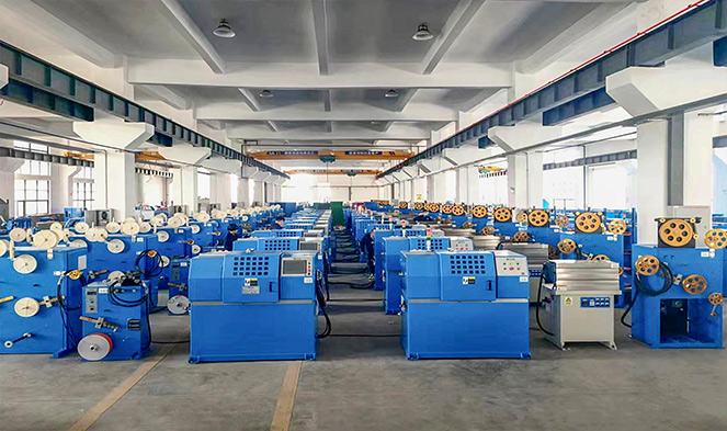
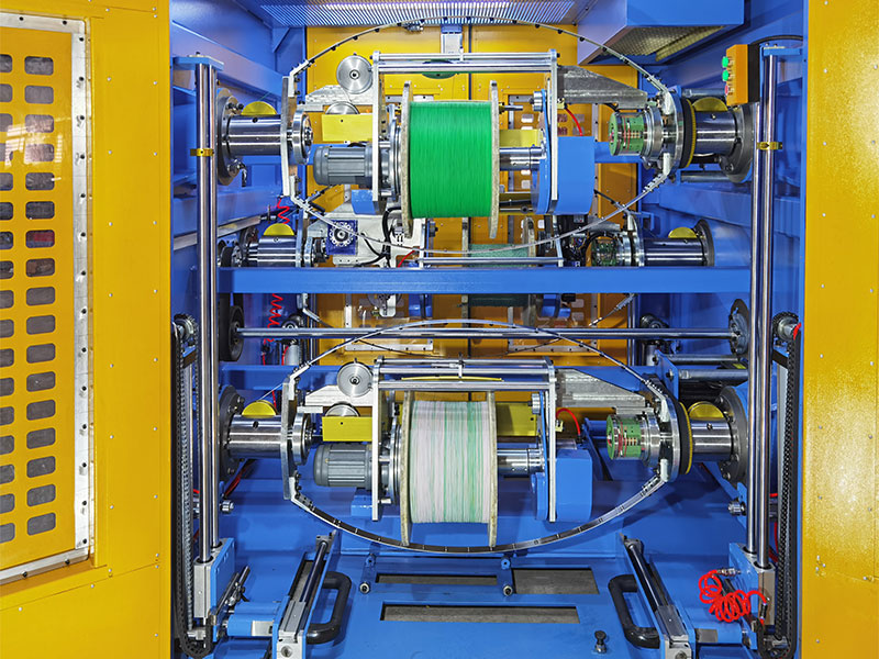
When you buy a spool of Cat6 or Cat6A cable, the quality of that cable is determined largely by how it was manufactured — specifically by the precision and condition of the wire and cable extruder used to apply insulation to the conductors, and the equipment used to control the twist lay of each pair.
A wire and cable extruder works by melting thermoplastic insulation compound (PVC, polyethylene, or LSZH material) and forcing it through a crosshead die around a moving conductor. The extruder controls the thickness and concentricity of the insulation layer with very tight tolerances. For Ethernet cable conductors, the insulation thickness directly affects the dielectric constant of the cable, which determines signal propagation velocity and impedance. Cat6 cable must maintain a characteristic impedance of 100 ohms ±15% across its frequency range — a specification that depends entirely on consistent insulation geometry from the cable extruder.
This is why there's a meaningful difference between premium brand-name cable and cheap no-name cable purchased from unverified suppliers. Cables made on poorly maintained or low-precision extruders may have inconsistent insulation thickness, off-center conductors (poor concentricity), or variable jacket wall thickness — all of which can cause a cable to fail performance standards even if it passes a basic continuity test. A cable that appears functional at 100 Mbps may fail to reliably sustain 1 Gbps or 10 Gbps due to these manufacturing inconsistencies.
Additionally, some budget cable manufacturers substitute copper-clad aluminum (CCA) conductors for solid copper. CCA has approximately 60% of the conductivity of pure copper, higher resistance, and significantly worse performance in Power over Ethernet (PoE) applications where the cable must carry both data and electrical power. Always verify that the cable you're buying is marked "BC" (bare copper) rather than "CCA" if performance and PoE compatibility matter.
Solid Core vs Stranded Conductor Cable: Which to Use
Ethernet cable is available in two conductor constructions: solid and stranded. This distinction matters more than most people realize.
Solid Conductor Cable
Each of the eight conductors is a single copper wire, typically 23 AWG for Cat6. Solid conductor cable is designed for permanent installations: running through walls, ceilings, conduit, and between patch panels and keystone jacks. It has superior electrical performance at high frequencies (lower attenuation, better crosstalk characteristics), but it's stiffer and more prone to conductor fatigue if repeatedly flexed. Solid conductor cable should not be used in applications where the cable is regularly moved, coiled, or flexed at the connectors.
Stranded Conductor Cable
Each conductor is made up of multiple thin copper strands bundled together, typically 7 strands per conductor. Stranded cable is softer, more flexible, and handles repeated bending without breaking — making it the right choice for patch cables: the short cable between a wall jack and a computer, or between a patch panel port and a switch port. Stranded cable has slightly higher resistance per unit length than solid cable, but at patch cable lengths (typically under 5 meters), this difference is negligible.
For DIY Ethernet cords used as patch cables, use stranded conductor cable. For permanent structured wiring runs inside walls, use solid conductor cable.
Shielded vs Unshielded Cable: When Shielding Matters
Most Ethernet cable used in homes and offices is UTP — Unshielded Twisted Pair. The twisted pair construction alone provides adequate noise rejection for most environments. Shielded cable adds one or more layers of metallic shielding — foil, braiding, or both — around the pairs or around the entire cable bundle.
| Cable Type | Shielding | Best For | Requires Grounded Connectors |
|---|---|---|---|
| UTP | None | Homes, standard offices | No |
| FTP / F/UTP | Overall foil wrap | Moderate EMI environments | Yes |
| STP / S/UTP | Overall braid | High EMI environments | Yes |
| SFTP / S/FTP | Foil per pair + overall braid | Industrial, data center, Cat7/8 | Yes |
Shielded cable requires shielded RJ45 connectors, and the shield must be connected to a proper earth ground at one end (typically at the patch panel or switch). An improperly grounded shield can actually introduce noise rather than eliminate it — a phenomenon called a ground loop. For home and standard office use, UTP cable with proper installation is sufficient for all modern gigabit and 10-gigabit applications.
Common Mistakes and How to Fix Them
Most failed DIY Ethernet cables trace back to a small set of recurring errors. Knowing them in advance saves time and wasted materials.
Wires Out of Order
The most common mistake. A transposed pair means the cable tester shows a "reversed" or "split pair" fault. A split pair is particularly insidious: the cable may link at low speeds but fail under load at gigabit because the pairs aren't correctly matched. Always double-check the wire sequence before crimping. There is no fix other than cutting off the connector and re-terminating.
Conductors Not Reaching the Front of the Connector
If the conductors don't reach the front wall of the RJ45 housing, the crimping pins won't pierce the insulation and make contact with the copper. The result is an open circuit on those pins. Look through the front of the connector in good light before crimping — you should see each conductor color at its corresponding pin slot. If not, push the cable in again and check for any conductor that's shorter or bent back.
Jacket Not Inside the Connector
The outer jacket must extend into the back of the RJ45 connector so that the strain relief tab grips it during crimping. If you stripped too much jacket, the conductors will be attached at the connector pins but the jacket will be floating free, creating a mechanically weak point that will fail when the cable is pulled or bent. Cut the cable back further, re-strip with less jacket removal, and re-terminate.
Insufficient Crimp Pressure
A crimp that looks complete but wasn't fully pressed can result in intermittent connections that are extremely hard to diagnose — the cable passes a basic tester one moment and fails under network load the next. Use a quality ratcheting crimper that guarantees full compression before releasing. If you're using a non-ratcheting tool and have any doubt, apply a second firm squeeze.
Excessive Untwisting of Pairs
Untwisting more than 13 mm of conductor at the termination point degrades crosstalk performance. This won't cause a cable to fail a continuity test, but it will cause a cable to fail Category 6 performance certification. For home use the impact may be invisible, but in high-density patch panel environments or long cable runs, excessive untwisting can be the difference between reliable 1 Gbps operation and frequent errors.
Outdoor and Specialty Ethernet Cables
Standard indoor Ethernet cable is not suitable for outdoor or direct burial use. The PVC jacket used in indoor cable absorbs moisture over time and degrades in UV light. For outdoor runs — between a house and a detached garage, for example — you need cable specifically rated for outdoor exposure.
Outdoor-rated Ethernet cable uses a UV-stabilized jacket compound, usually black polyethylene or a UV-resistant PVC blend, applied via a wire and cable extruder formulated for environmental resistance. Some outdoor cables also include a water-blocking gel or flooding compound around the pairs to prevent moisture migration into the cable core.
Direct-burial cable goes one step further: it's designed to be buried in the ground without conduit. It typically has a thicker jacket, a gel-filled core, and sometimes an additional armor layer (steel or aluminum) to protect against mechanical damage from rocks or rodents. The outer jacket on armored cable is produced in two layers by the cable extruder — an inner bedding layer over the armor and an outer protective layer — making it significantly more durable than standard cable.
For aerial installations (running between buildings via a cable strung between poles), you need self-supporting Ethernet cable, which includes a steel messenger wire integrated into the jacket or bundled alongside the cable. This messenger wire bears the mechanical tension of the span, protecting the Ethernet conductors from stretching.
When terminating outdoor or direct-burial cable with RJ45 connectors at transition points (where the cable enters a building, for example), use weatherproof junction boxes or properly sealed gel-filled splice kits to prevent moisture ingress at the connection points. The RJ45 connectors themselves are not waterproof and should never be left exposed to weather.
Power over Ethernet Considerations When Making Your Own Cables
Power over Ethernet (PoE) delivers DC electrical power through the same cable that carries network data, eliminating the need for a separate power supply at devices like IP cameras, wireless access points, VoIP phones, and IoT sensors. If you're making Ethernet cords that will carry PoE, there are additional factors to consider.
The IEEE 802.3bt standard (PoE++) can deliver up to 90 watts of power per port across all four pairs. At these power levels, conductor resistance matters significantly. Power dissipation in the cable (I²R losses) causes the cable to heat up, and a cable that heats up in a bundle with other cables heats up even more. The 802.3bt standard includes derating guidelines specifying how close to the maximum distance rating you can reliably operate bundled PoE cables.
Use only solid bare copper conductors for PoE applications. Copper-clad aluminum conductors are explicitly not recommended for PoE because of their higher resistance and their tendency to fail at crimp points under the thermal cycling that PoE current causes. Some PoE injectors have been known to damage or destroy CCA cables over time.
For high-power PoE++ applications, Cat6A cable is preferred over Cat6 not only for its 10 Gbps performance but because its larger-gauge conductors (23 AWG, same as Cat6, but with better construction consistency) and its tighter manufacturing tolerances — including more consistent insulation geometry from the cable extruder during production — result in lower and more predictable resistance per unit length.
Terminating to Wall Jacks and Patch Panels Instead of RJ45 Plugs
Not every Ethernet cable needs an RJ45 crimp connector. Structured wiring installations typically terminate permanent cable runs to keystone jacks mounted in wall plates, or to 110-punch patch panel ports. Both types of termination use a punch-down tool rather than a crimper.
A punch-down tool seats and trims the conductor into a slotted terminal in a single motion. The slot cuts through the conductor insulation and makes contact with the bare copper, similar to how the IDC (insulation displacement contact) pins in an RJ45 connector work during crimping. Keystone jacks are labeled with both T568A and T568B color codes, so you simply follow the color diagram printed on the jack itself.
Use a 110 punch-down blade rated for the cable category you're terminating. Blades worn from use or of incorrect type can produce poor terminations that pass continuity testing but fail performance certification. High-quality Cat6A keystone jacks use a hinged or toolless design that maintains the pair twist as close to the termination point as possible, preserving the crosstalk performance that the cable's construction — carefully controlled during the wire and cable extruder process at the factory — was engineered to achieve.


