E-mail: info@gem-cablesolution.com
 Address: No.8 Yuefeng Rd, High Tech Zone, Dongtai, Jiangsu, China | No.109 Qilin East Rd, Daning, Humen, Dongguan, Guangdong, China.
 English
  English
 русский
 日本語
日本語 Español
 عربى
عربى 中文简体
中文简体



For Twinax cables in AI servers, lowering the effective Dk of the insulation (air ≈1, FEP≈2.1) is key to reducing high-frequency loss, skew, and impedance instability. Five low-cost manufacturing approaches have been developed to achieve this.
| Construction | Dielectric Type | Key Advantages | Major Limitations | Mainstream Data Rates | ||||||||||
| EPTFE Wrap | Microporous Wrap | Lowest insertion loss | High material & process cost | 448G | ||||||||||
| Dual FEP Extrusion | Double layer solid FEP insulation | Mature, mechanically robust | Relatively higher attenuation | ≤224G | ||||||||||
| Dual-Conductor Co-extrusion | Monolithic solid dielectric | Extremely low intrapair skew | High loss due to solid dielectric | Up to 224G (short distance) | ||||||||||
| Physically Foamed FEP | Closed cell micro foam | Low‑loss & proven | Costly foaming equipment; performance drifts under bending | 224G ~ 448G | ||||||||||
| Longitudinal Air-Gap (Lotus-Root) Core | Longitudinal air channels | Balances performance and cost | Limited crush resistance | 448G |
EPTFE Taping Construction Solution
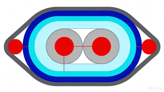
Hierarchical structure
Red:Signal Conductors (Silver-Plated Copper / Copper Alloy)
Gray:Inner Non-Foamed (Solid) FEP Primary Insulation
Light Blue:Main EPTFE Wrap Insulation Body
Dark Blue:Outer Protective Taping / Shielding Layers (Cu-Foil, Al-Foil, and other structural components)
Small Red Circles on Sides:Grounding / Drain Wire Structure
1.Process Principle
EPTFE tape is wound onto the conductor under controlled tension and overlap. The trapped air within its microporous structure yields a low effective Dk of ≈1.4–1.6."
2.Key Advantages
This construction offers ultra-low dielectric loss, very low insertion loss, high-temperature resistance, and an effective Dk close to that of air.
3.Applications
448G/800G ultra-fast Twinax, long-haul high-speed links, and IL-critical high-end compute interconnects.
Dual-Layer FEP Extrusion Solution
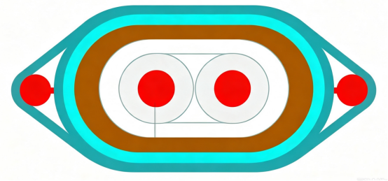
Structural Layering (from inside out)
Two signal conductors of silver-plated copper or copper alloy.
Inner layer: Solid FEP primary insulation, single-core extruded.
Outer layer: Common FEP over-jacket, co-extruded over both conductors.
Grounding wires on both sides of the assembly.
1.Process Principle
Two-step extrusion: solid FEP is first extruded over each conductor individually, then the two insulated cores are placed side-by-side and over-extruded with an outer FEP layer, forming a dual-layer solid fluoroplastic insulation.
2.Advantages
Stable dimensions, excellent chemical resistance and mechanical strength, mature process with high yield.
3. Application Scenarios
Up to 224G medium-/short-reach high-speed cables; industrial high-temp high-speed interconnects; moderate-cost general-purpose high-speed differential links.
Twin Conductor Co-Extrusion (monolithic)
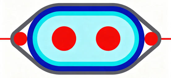
Structural Layering (from inside out):
Two parallel signal conductors
Single-pass extruded monolithic solid FEP/PFA dielectric over both conductors, with a thin outer protective tape.
Grounding wires positioned on both sides
1.Process Principle
A specially designed elliptical twin-core die enables single-pass extrusion, embedding both conductors in a common dielectric and locking their center pitch during extrusion.
2.Advantages
Tight conductor spacing consistency yields extremely low intra-pair skew; fewer process steps and lower cost than two-step FEP extrusion; excellent impedance uniformity.
3.Application Scenarios
Short-reach high-speed cables, PCB interconnects, backplane links, and low intra-pair skew links.
Physically Foamed FEP
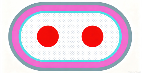
Structural Layering (from inside out):
Twin signal conductors
Microcellular FEP insulation.
Solid FEP outer skin.
1.Process Principle
During extrusion, high-pressure nitrogen is injected into molten FEP, creating closed-cell microvoids that dilute the dielectric with air and lower the overall Dk.
2.Advantages
Lower Dk and attenuation than solid FEP; controlled impedance.
3.Applications
224G–448G data center high-speed cables for medium- to long-reach
interconnects.
Lotus Root Hole Structure
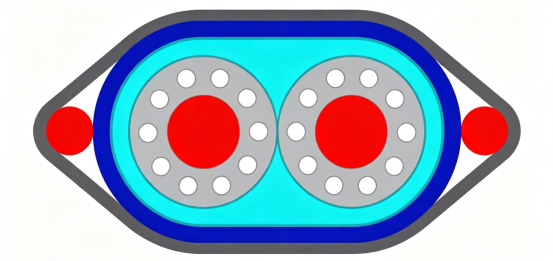
Structural Layering (from inside out)
Two signal conductors
Circumferential longitudinal void channels around the conductor (continuous air cavities along the cable length, like lotus root holes).
Outer solid FEP insulation
Side positioning support wires
1.Process Principle
Lotus-root die creates continuous air channels (interconnected) for low Dk, boosting performance – distinct from foamed FEP's closed-cell voids.
2.Advantages
Less bending impedance change vs. physical foam at same loss; lower cost; excellent HF SI; no high-pressure foaming gear.
3.Applications
PCIe 6.0, 448G next-gen high-speed copper cables – emerging solution for compute servers.
Empower your production line with true high-speed cable manufacturing capability.
Click the link below to request your customized equipment solution. ↓
TWINAXIAL HIGH SPEED COPPER CABLE
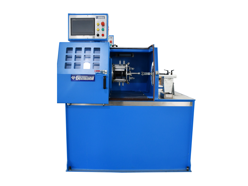
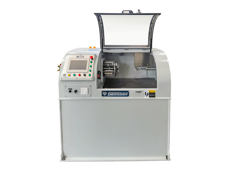
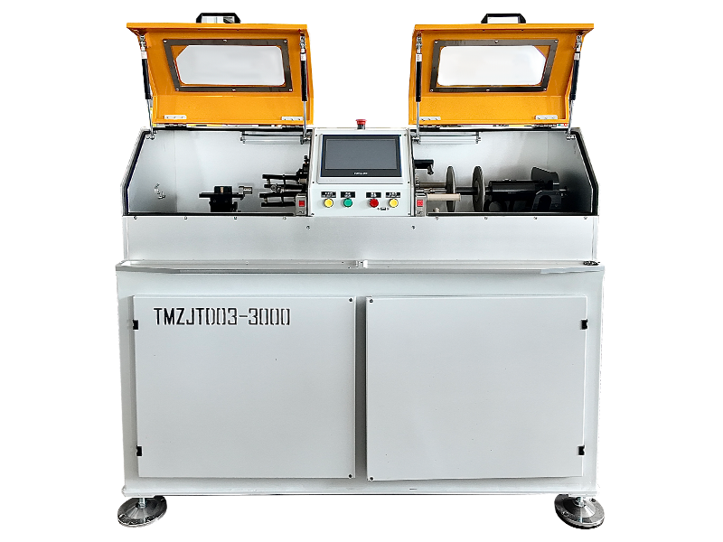
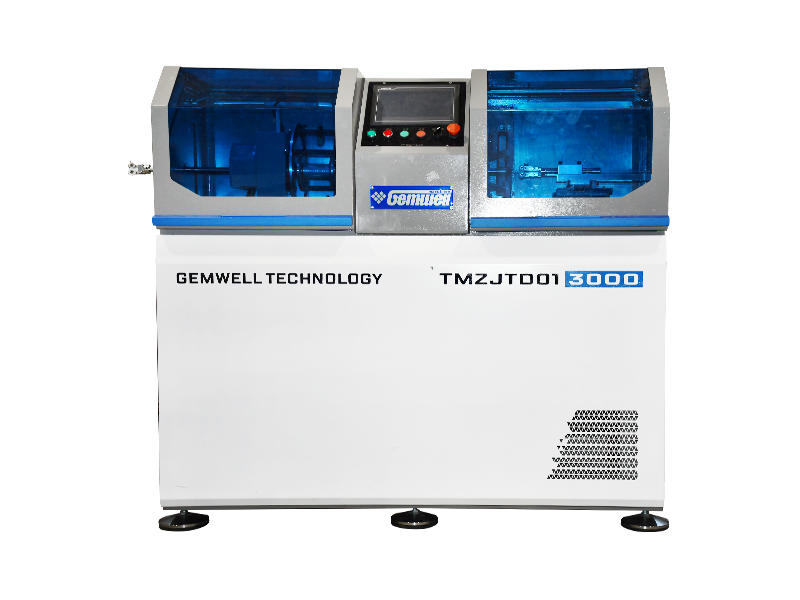
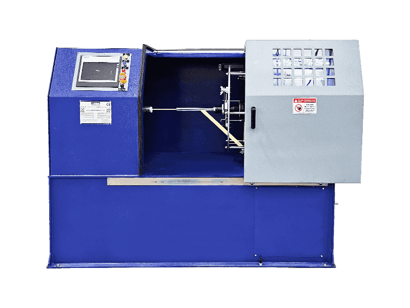
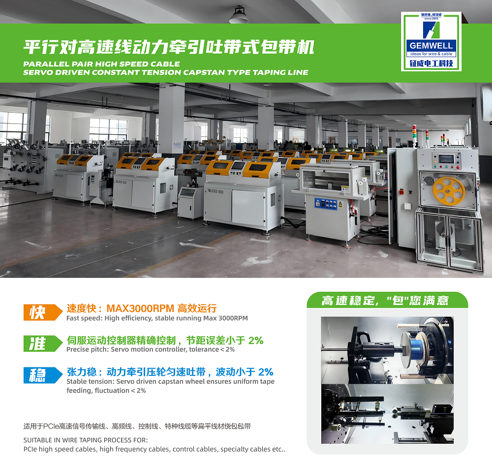
SERVO DRIVEN CONSTANT TENSION TAPING LINE - CAPSTAN TYPE
Servo-controlled tape wrapping machine with stable tension supports foils and PTFE tape for uniform shielding and impedance
stability.
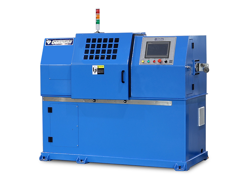
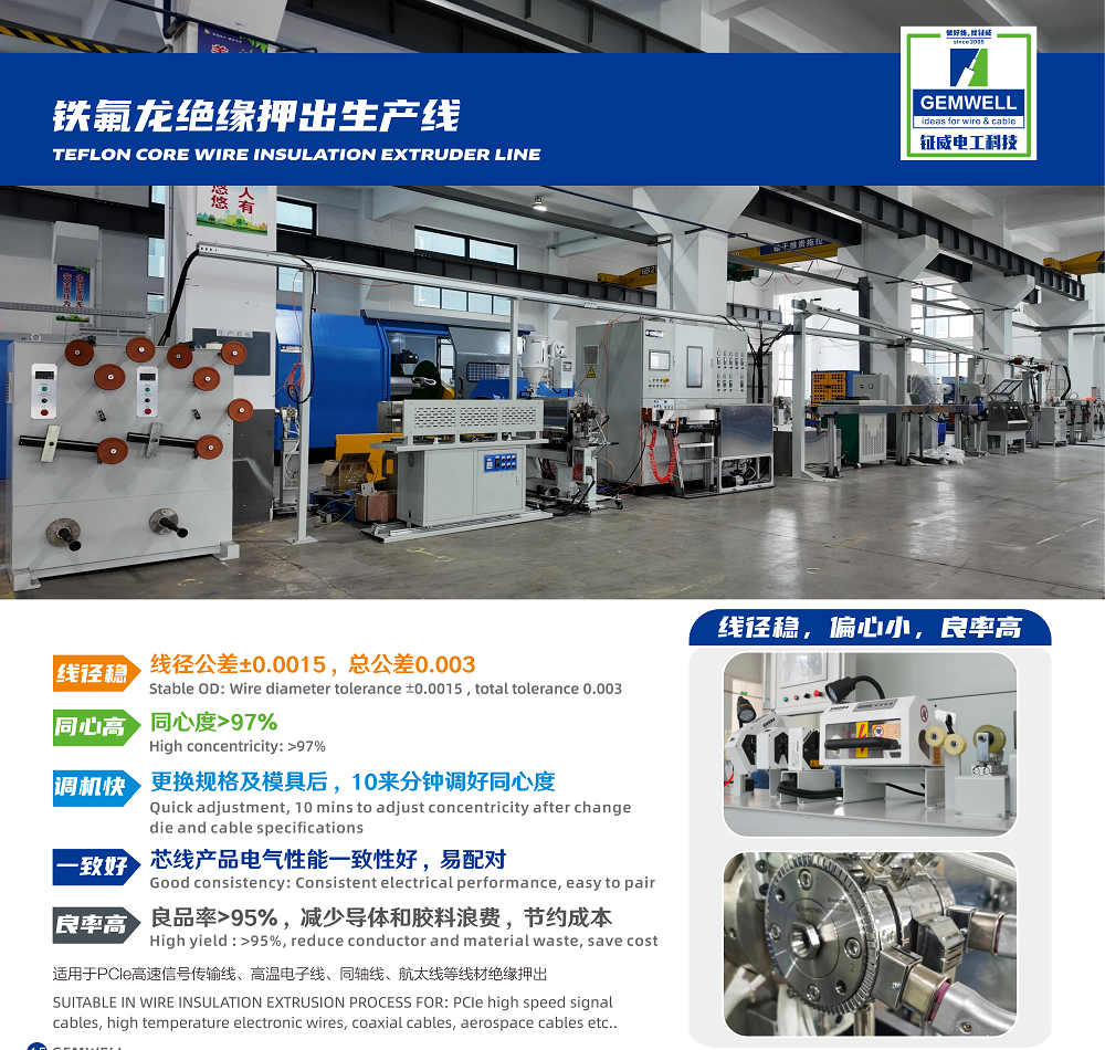
TEFLON CORE WIRE INSULATION EXTRUDER LINE
Precision-extruded FEP/PFA insulation reduces Dk and high-frequency loss, ensuring signal integrity.
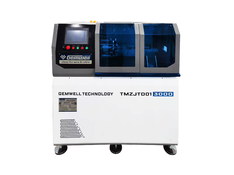
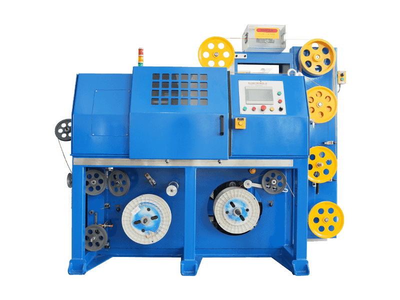
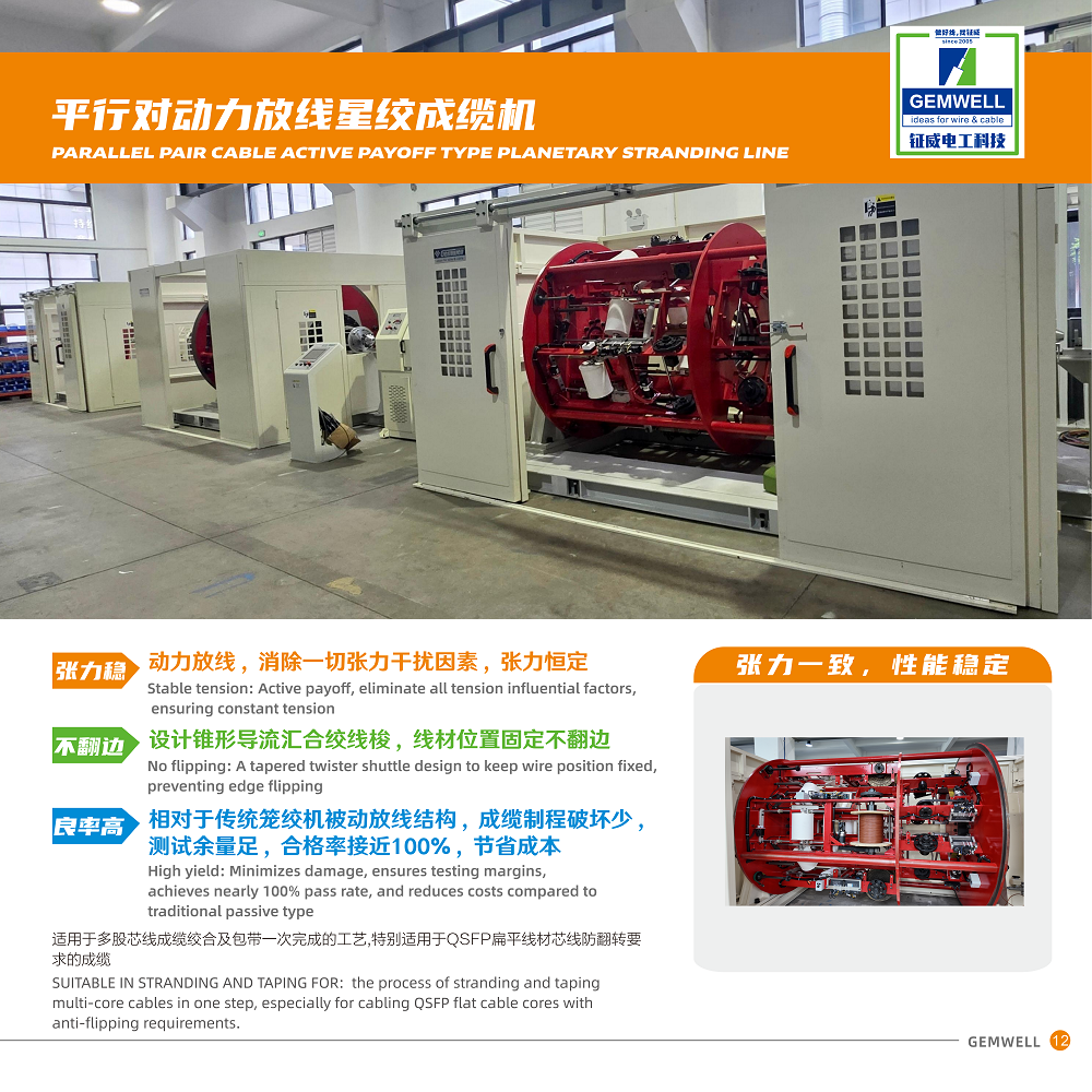
AI HIGH SPEED CABLE PARALLEL PAIR CABLEACTIVE PAYOFF TYPE PLANETARY STRANDING LINE
Planetary stranding of multi-core twinaxial cables ensures symmetry and precise pitch for stable high-speed parallel transmission.
 Related Products