E-mail: info@gem-cablesolution.com
 Address: No.8 Yuefeng Rd, High Tech Zone, Dongtai, Jiangsu, China | No.109 Qilin East Rd, Daning, Humen, Dongguan, Guangdong, China.
 English
  English
 русский
 日本語
日本語 Español
 عربى
عربى 中文简体
中文简体



Content
- 1 Global Standards for Conductor Stranding: The Direct Answer
- 2 Why Conductor Stranding Standards Exist
- 3 The Main Standard Families and How They Compare
- 4 IEC 60228 Conductor Classes and What They Tell a Buyer
- 5 Stranding Configurations: Concentric, Bunch, Rope, Compacted, and Sector
- 6 Lay Length, Lay Ratio, and Lay Direction: The Tolerances That Matter
- 7 How Stranding Compliance Is Verified
- 8 What a Cable Purchasing Specification Should Say
- 9 Frequently Asked Questions about Conductor Stranding Standards
- 9.1 What exactly do global standards for conductor stranding include?
- 9.2 What is the difference between Class 2 and Class 5 stranding?
- 9.3 Why is lay length important?
- 9.4 Which standard should a buyer specify: IEC 60228 or ASTM B8?
- 9.5 Does compacting a conductor change its DC resistance?
- 9.6 Can one twisting machine meet several international standards at the same time?
- 10 From Standard Sheet to Shop Floor: Choosing Equipment That Holds the Tolerance
Global Standards for Conductor Stranding: The Direct Answer
If you are reading this because an exam question asked "Global standards for conductor stranding include ___ resistance and ___ cross-sectional area," the correct short answer is maximum DC resistance and minimum cross-sectional area. That wording appears in training materials based on IEC 60228, because the standard controls stranding by placing an upper limit on DC resistance and a lower limit on cross-section for every declared nominal size.
For a cable engineer who has to buy, build, or qualify a conductor, that two-part answer is a necessary start but not a complete one. Global standards for conductor stranding include construction requirements as well as electrical limits. A strand package is defined by wire diameter, number of wires, lay length, lay ratio, lay direction, conductor class, material grade, surface condition, and in some cases compaction level. Resistance limits tell you whether the conductor conducts; the construction rules tell you whether it will bend, terminate, and survive the application it is built for.
| Parameter | What It Controls | Typical Requirement |
|---|---|---|
| Wire diameter | Individual strand size, overall flexibility, and resistance consistency | Specified in mm with tolerance; e.g., 1.83 mm for a common 50 mm² Class 2 construction |
| Number of wires | Flexibility, mechanical strength, and current distribution | Minimum wire count per class; e.g., 19 wires minimum for 50 mm² Class 2 |
| Lay length | Axial distance for one full twist of the strand group | Usually in mm or as a multiple of the conductor outside diameter |
| Lay ratio | Relationship between lay length and conductor diameter | Commonly 8:1 to 16:1 for round concentric stranding |
| Lay direction | Right-hand or left-hand twist direction | Usually right-hand for the outer layer unless the drawing says otherwise |
| Conductor class | Flexibility level of the finished conductor | Class 1, 2, 5, or 6 under IEC 60228 |
| Material and surface | Conductivity, corrosion resistance, surface finish | Annealed copper, aluminium, or tinned copper with clean, burr-free surfaces |
| Compactness | Diameter reduction for the same cross-section | Compact strands typically reduce diameter by 3 to 8 percent |
Why Conductor Stranding Standards Exist
Stranding exists because a solid wire of the same cross-section would be too stiff, too hard to terminate, and too sensitive to repeated bending. In a 50 mm² Class 2 conductor, the minimum wire count of 19 strands required by IEC 60228 turns a rigid rod-like element into a bundle that can be bent, coiled, and terminated with standard lugs. That is the mechanical reason behind every stranding standard.
There is also an electrical reason. At higher frequencies, skin effect pushes current toward the outer surface of a conductor. A stranded conductor with multiple smaller wires follows a cable contour more cleanly and limits the air gaps that appear when a solid conductor is forced to bend. However, stranding must not push DC resistance above the allowed ceiling, which is exactly why IEC 60228 sets maximum resistance values for every class and nominal cross-section.
Ignoring these limits creates measurable problems. If resistance exceeds the maximum, the cable runs hotter and voltage drop grows beyond the calculated value. If the wire count is lower than the minimum, the conductor may fail a flex test or open up at a termination point. If the lay length drifts, elongation mismatches can cause kinking or bird-caging when the cable is pulled into a conduit. Field failures, rejected production lots, and delayed projects are the usual consequences.
The Main Standard Families and How They Compare
No single document owns the subject of conductor stranding. The most widely used international baseline is IEC 60228, which is adopted in Europe as BS EN 60228, mirrored in Germany as VDE 0295, and matched in China by GB/T 3956. In North America, the practical references are ASTM B8 for concentric-lay-stranded copper conductors, ASTM B787 for 19-wire combination unilay conductors, ASTM B496 for compact round stranded copper conductors, and ASTM B172 for rope-lay-stranded conductors with bunch-stranded members.
| Standard | Region / Scope | What It Covers | When to Use It |
|---|---|---|---|
| IEC 60228 | International | Conductors of insulated cables, Classes 1, 2, 5, and 6 | Baseline for most global cable specifications |
| BS EN 60228 | UK / Europe | Same technical content as IEC 60228 | UK and EU projects requiring a harmonized EN reference |
| VDE 0295 | Germany | German adoption of IEC 60228 | German and export-oriented specifications |
| GB/T 3956 | China | Equivalent to IEC 60228 | Chinese production, domestic sales, and import inspection |
| ASTM B8 | United States | Concentric-lay-stranded copper conductors | North American building wire and general-purpose cables |
| ASTM B787 | United States | 19-wire combination unilay conductors | Thin-insulation designs with good flexibility |
| ASTM B496 | United States | Compact round stranded copper conductors | Compact designs that reduce finished cable diameter |
| ASTM B172 | United States | Rope-lay-stranded conductors with bunch-stranded members | Flexible cords and heavy flex applications |
Although the document numbers differ, the logic is consistent. Each standard assigns a class, sets a minimum wire count, limits diameter variation, and caps DC resistance. A well-written purchase order names one of these standards explicitly, because "ASTM-compliant" and "IEC-compliant" are not interchangeable labels.
IEC 60228 Conductor Classes and What They Tell a Buyer
IEC 60228 divides conductors into four classes. Class 1 is solid. Class 2 is the standard stranded conductor for fixed installations. Class 5 is flexible, and Class 6 is extra flexible. The class number directly controls how many wires are used and how fine those wires are.
| Class | Construction | Flexibility | Typical Applications |
|---|---|---|---|
| Class 1 | Solid, single wire | Very low | Fixed installations, rigid wiring systems |
| Class 2 | Small number of larger strands in concentric layers | Low to moderate | Power cables in fixed installations |
| Class 5 | Many fine wires | High | Equipment wiring, flexible cords, servo and control cables |
| Class 6 | Even finer wires than Class 5 | Very high | Continuous flex, robotics, drag chains, machine tools |
The numbers make the trade-off visible. For a 1.5 mm² annealed copper conductor, IEC 60228 sets a maximum DC resistance of 12.1 mΩ/m for Class 1 and Class 2, and 13.3 mΩ/m for Class 5 and Class 6 at 20 °C. The higher allowance for flexible classes exists because fine wires create a slightly longer current path and more inter-strand contact resistance. For a 2.5 mm² Class 5 conductor, the minimum number of wires is 50, compared with 7 wires for a Class 2 conductor of the same nominal size.
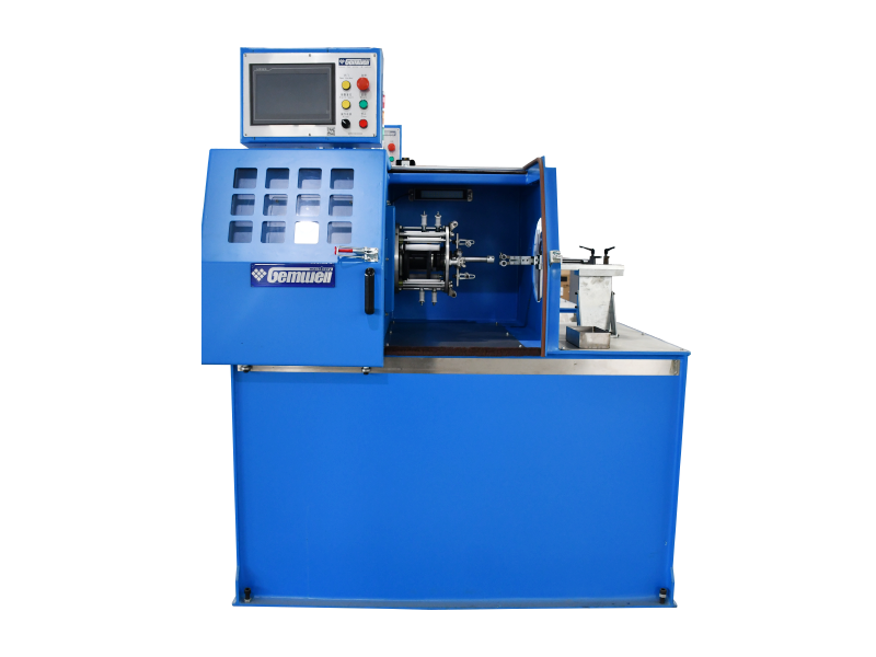
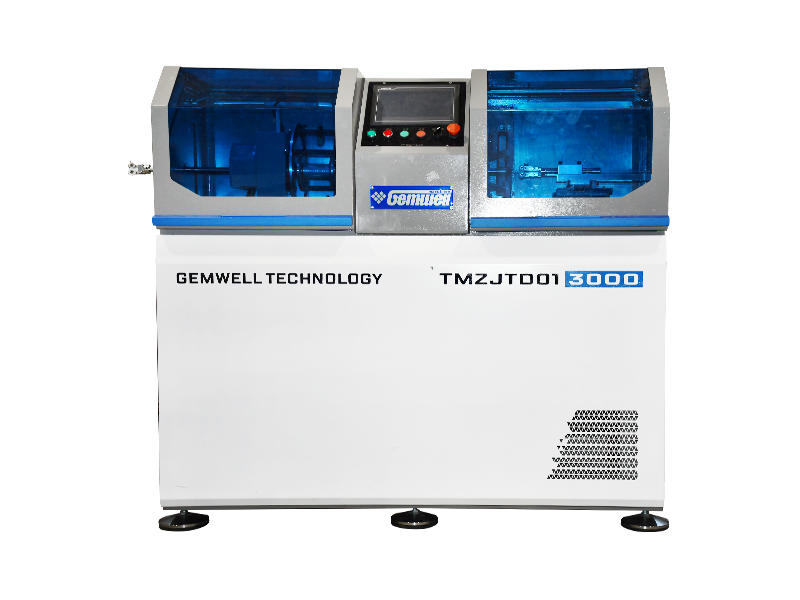
Flexible classes appear constantly in data and automotive cables, and that is where stranding meets pair twisting. A Class 5 conductor feeding an industrial Ethernet or automotive data cable must stay flexible without building up torsional stress during pairing. Many cable plants use a four-core industrial Ethernet cable torsion-free twisting machine at this stage, because it twists four cores without rotating the cores themselves, preserving the conductor construction the standard defines.
 Back Twist Pair Twisting Machine for Four Cores Industrial Ethernet Data Cable Gemwell Electrical Technology Co., Ltd is a China Back Twist Pair Twisting Machine for Four Cores Industrial Ethernet Data Cable manufac...View Product →
Stranding Configurations: Concentric, Bunch, Rope, Compacted, and Sector
The conductor class sets the flexibility target; the configuration sets the geometry. Each configuration changes how the conductor behaves in bending, how it occupies space, and how easily it can be terminated.
Concentric-Lay Stranding
In a concentric-lay construction, wires are arranged in layers around a center wire, with successive layers laid in opposite directions. Standard wire counts follow the 1+6, 1+6+12, and 1+6+12+18 pattern. The result is a stable, round conductor that resists deformation, which is why ASTM B8 and IEC 60228 Class 2 both default to this configuration for power cables.
Bunch Stranding
Bunch stranding twists all wires together in the same direction without a geometric layer pattern. It is faster and cheaper than concentric stranding, but the finished conductor has less geometric stability. Bunched conductors are common in flexible cords, automotive wiring, and other applications where the conductor will be terminated quickly and flexed regularly.
Rope-Lay Stranding
Rope-lay stranding first forms small bunched groups, then lays those groups around a core. This two-stage construction is the standard answer for high flex life and mechanical strength. ASTM B172 defines this family, and it shows up in mining cables, crane cables, and other applications where a cable must survive constant bending and tension.
Compacted and Sector-Shaped Stranding
Compacted strand is passed through rollers or a die after stranding to reduce the outside diameter, typically by 3 to 8 percent, while keeping the same cross-section. Sector-shaped conductors go further and are pressed into a sector profile so that three-core cables can fit into a smaller overall diameter. Both options reduce cable weight and material cost, but they demand tighter process control during the stranding step.
| Configuration | Assembly Principle | Wire Count Example | Best For |
|---|---|---|---|
| Concentric | Layers laid around a center wire in opposite directions | 7, 19, 37 | Power cables that need stable round geometry |
| Bunch | All wires twisted in one direction | 7 to 100+ | Flexible equipment wires and automotive leads |
| Rope-lay | Bunched groups laid around a core | 7 groups of 7, 19 groups of 19 | Mining, hoisting, and high-flex applications |
| Compacted | Concentric or bunched strand drawn to reduced diameter | 7, 19, 37 | Small-diameter power and control cables |
| Sector-shaped | Strand pressed into a sector profile | 7 or 19 per sector | Fixed three-phase power cables with reduced diameter |
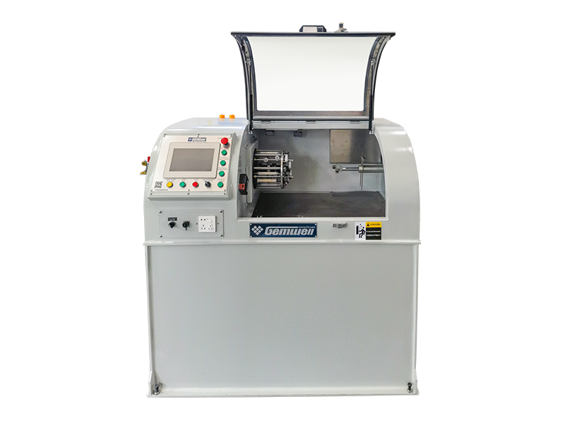
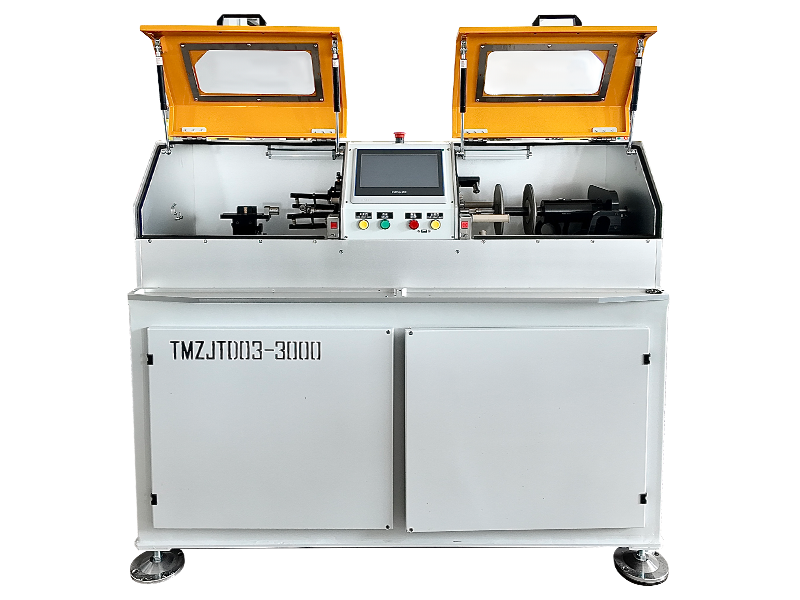
Concentric and unilay constructions place the heaviest demand on tension stability. If tension varies during the run, the outside diameter and lay length drift. Equipment such as the heavy-duty separated-arm single-twist machine with external draw and power take-up is built to hold that tension through the entire twist cycle, which is exactly what these configurations need at the end of a production line.
Heavy-Duty Split Type Cantilever Single Twisting Machine (External Capstan and TGemwell Electrical Technology Co., Ltd is a China Heavy-Duty Split Type Cantilever Single Twisting Machine (External Capstan and Torque T...View Product →
For a factory producing paired or multi-core constructions after stranding, choosing the geometry stage is half the work. Many production teams review the wire pair twisting machine lineup during planning, because pair twist interacts with the conductor's own lay and can amplify a small stranding error.
Lay Length, Lay Ratio, and Lay Direction: The Tolerances That Matter
Lay length is the axial distance a conductor travels as the strand group completes one full 360-degree twist. Lay ratio is the lay length divided by the mean diameter of the conductor. Both values appear in standards and drawings, and both are frequently misunderstood on the shop floor.
A shorter lay consumes more wire per metre of conductor, which increases weight and slightly raises DC resistance. A longer lay reduces material use but can make the bundle less stable under bending and easier to open at terminations. For round concentric constructions, typical lay ratios sit between 8:1 and 16:1, and many plant standards specify 10:1 to 14:1 as a compromise. Lay direction is written as right-hand or left-hand; the outer layer is usually right-hand unless the drawing explicitly says otherwise.
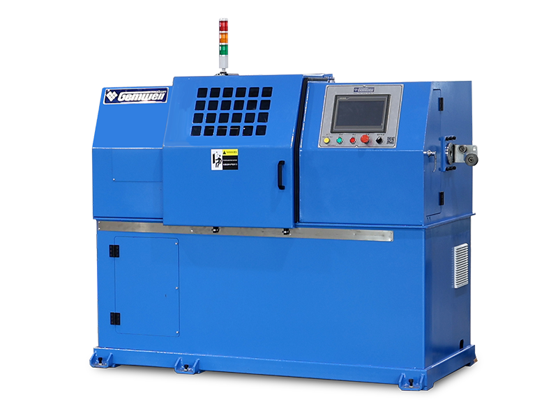
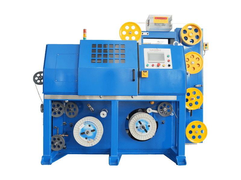
Network cable production is where lay tolerance becomes strict, because each pair must keep its own twist rhythm to control crosstalk and delay skew. A network cable three-pitch integrated triple twisting machine solves a common production problem by applying three pitch stages in a single pass, which removes the re-tensioning steps that normally cause lay length drift between operations.
Integrated Type Triple Pitch Pair Twisting Machine for Network Cable ManufactureGemwell Electrical Technology Co., Ltd is a China Integrated Type Triple Pitch Pair Twisting Machine for Network Cable manufacturers and ...View Product →How Stranding Compliance Is Verified
Global standards do not rely on visual judgement alone. They set measurable acceptance criteria, and every verification test points back to resistance or geometry. The most important check is DC resistance measured at 20 °C, because it is the fastest reliable indicator of whether the conductor material and cross-section are correct.
| Test | Reference | Typical Acceptance | Purpose |
|---|---|---|---|
| DC resistance at 20 °C | IEC 60228 | Maximum value per class and nominal cross-section | Confirms conductivity and effective cross-section |
| Wire count and wire diameter | Purchase order and drawing | Exact count, diameter within tolerance | Detects missing or wrong-size wires |
| Lay length measurement | Manufacturer specification | Within plus or minus 5 percent of declared lay | Checks geometry consistency along the length |
| Surface and continuity inspection | In-process quality control | No burrs, no broken wires, no exposed fines | Prevents termination faults and shorts |
Resistance values in IEC 60228 are maximum values, not nominal targets. That means a 1.5 mm² Class 2 conductor measuring 12.0 mΩ/m is acceptable, while 12.3 mΩ/m fails even if the difference looks negligible on a meter. The same discipline applies to wire count: a missing wire may not change the resistance enough to notice, but it can change the flex life and create a field failure months later.
What a Cable Purchasing Specification Should Say
Most stranding defects reach the customer because the purchase order was vague. A clear specification removes the guesswork, and it is the cheapest quality tool a cable buyer has. The checklist below works for power cables, control cables, and flexible data cables alike.
- Name the standard and edition, such as IEC 60228 Third Edition.
- State the conductor material: annealed copper, tinned copper, or aluminium.
- Specify the conductor class, with a reason if it is not Class 2.
- Declare the number of wires and the nominal wire diameter.
- Declare the lay length or lay ratio, with the allowed tolerance.
- Declare the lay direction of the outer layer.
- Define the overall diameter tolerance and any compaction target.
- Require a DC resistance test report measured at 20 °C.
- Specify surface conditions: clean, dry, free from oxidation and burrs.
- For Class 5 and Class 6 conductors, add any flex life requirement from the final application.
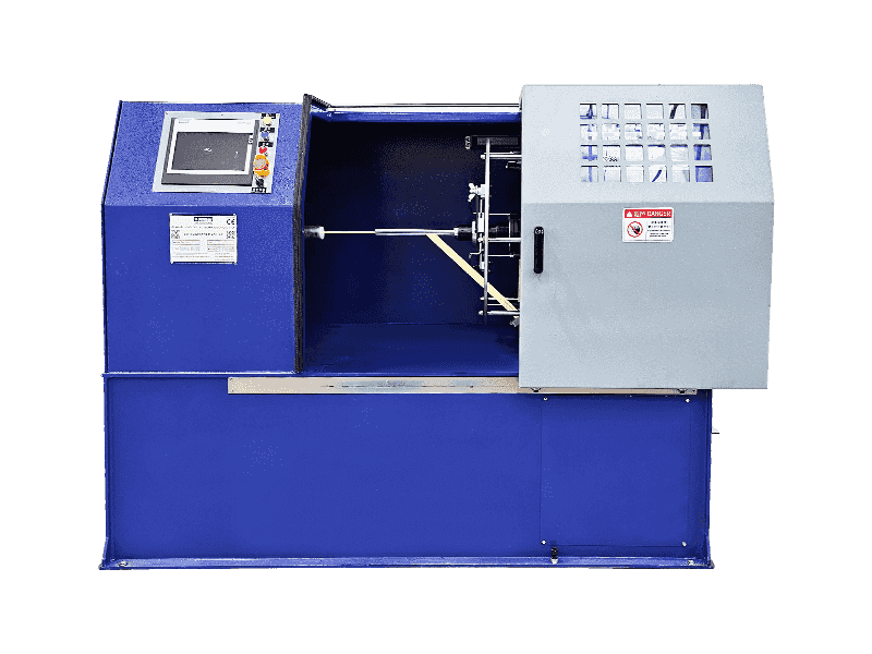
Once the specification is final, the next decision is which production equipment can hold those numbers. Comparing the cantilever single twisting machine range against the declared lay ratio and diameter tolerances is a practical first step. It is also worth reading the field-level operational notes on stranding machines to understand which machine adjustments are most likely to change lay length during a production run.
Frequently Asked Questions about Conductor Stranding Standards
What exactly do global standards for conductor stranding include?
They include maximum DC resistance and minimum cross-sectional area as the two primary acceptance limits. They also include construction requirements: number of wires, wire diameter, lay length, lay ratio, lay direction, conductor class, material grade, surface condition, and compaction level for compact designs.
What is the difference between Class 2 and Class 5 stranding?
Class 2 uses fewer, larger wires and is meant for fixed installations. Class 5 uses many fine wires and is meant for flexible use. As a reference, a 2.5 mm² Class 5 conductor requires a minimum of 50 wires, while the same nominal size in Class 2 requires only 7 wires. Class 5 also receives a higher maximum DC resistance allowance under IEC 60228.
Why is lay length important?
Lay length affects the total conductor length, weight, DC resistance, and flexibility. A shorter lay consumes more wire per metre and raises resistance slightly; a longer lay is more efficient but can reduce bending stability and open up under stress. Both effects are why standards and drawings treat it as a controlled dimension.
Which standard should a buyer specify: IEC 60228 or ASTM B8?
Use IEC 60228 for most international projects, BS EN 60228 for UK and EU contracts, GB/T 3956 for China-related procurement, and ASTM B8 for North American building wire and general-purpose copper conductors. If the cable will be exported, name one primary standard and list the others as equivalent references.
Does compacting a conductor change its DC resistance?
Compaction reduces the outside diameter by roughly 3 to 8 percent while keeping the cross-sectional area stable, so DC resistance does not change significantly if the process is controlled correctly. The bigger risk is that aggressive compaction work-hardens the strands and raises resistance, which is why compact conductors still have to pass the same maximum resistance test as non-compact designs.
Can one twisting machine meet several international standards at the same time?
Yes, if the machine offers adjustable lay length, precise tension control, and a stable take-up system. Standards differ mainly in class, wire count, and resistance values, which are set by the conductor design rather than by the machine. The machine has to hold the geometry: consistent tension, correct lay ratio, and no strand damage during the twist cycle.
From Standard Sheet to Shop Floor: Choosing Equipment That Holds the Tolerance
A standard on paper is only as good as the production line that has to hold it. The most common failure in real cable plants is not an unknown standard; it is a machine that cannot keep tension stable over a full reel, or a twisting process that changes the lay length between the head and the take-up. That is why equipment selection matters as much as specification writing.
For fixed-installation power cables, a heavy-duty single-twist machine with external draw and power take-up keeps the conductor under constant tension through the full twist cycle. For flexible data and automotive cables, torsion-free twisting prevents the core from rotating while pairs are formed, which protects the conductor geometry that IEC Class 5 and Class 6 specify. For network cables, a three-pitch integrated machine removes the re-tensioning steps that create lay variation between operations.
When you sit down with a supplier to review a new cable design, keep the original quiz question in mind. Global standards for conductor stranding include maximum DC resistance and minimum cross-sectional area, but the full engineering answer lives in the details: wire count, lay length, lay ratio, lay direction, conductor class, material, surface quality, and the production equipment that keeps all of them inside tolerance. Ask for the measured resistance at 20 °C, ask for the wire count and lay length on the test report, and make sure the twisting machine in your factory is capable of the same precision the standard demands.
 Related Products