E-mail: info@gem-cablesolution.com
 Address: No.8 Yuefeng Rd, High Tech Zone, Dongtai, Jiangsu, China | No.109 Qilin East Rd, Daning, Humen, Dongguan, Guangdong, China.
 English
  English
 русский
 日本語
日本語 Español
 عربى
عربى 中文简体
中文简体



Content
- 1 How Fiber Optic Cable Is Made: The Short Answer
- 2 The Raw Materials Behind Every Optical Fiber
- 3 Preform Fabrication: Building the Glass Blueprint
- 4 Fiber Drawing: Turning Glass Rods Into Hair-Thin Strands
- 5 Single-Mode vs Multi-Mode: How the Manufacturing Process Differs
- 6 Coating and Buffering the Bare Fiber
- 7 Stranding and Core Assembly
- 8 Armoring: Adding Rodent and Crush Protection
- 9 Jacketing and Sheathing: Where Extrusion Technology Takes Over
- 10 Inside a Wire and Cable Sheath Extrusion Machine
- 11 Comparing Fiber Optic Cable Sheath Materials
- 12 What to Look For When Choosing an Extrusion Line for Optical Cable
- 13 Automation and In-Line Monitoring on Modern Production Lines
- 14 Quality Testing Before the Cable Ships
- 15 Common Manufacturing Defects and How They Are Prevented
- 16 Frequently Asked Questions
How Fiber Optic Cable Is Made: The Short Answer
Fiber optic cable is built in five main stages: a glass preform is fabricated from ultra-pure silica, the preform is drawn into a hair-thin fiber inside a drawing tower, the bare fiber is coated and buffered for protection, multiple fibers are stranded around a central strength member, and the finished core is jacketed through an extrusion process. The jacketing stage is where a wire and cable sheath extrusion machine becomes the central piece of equipment, since it melts and applies the outer polymer layer that protects the fiber core from moisture, crushing, and UV exposure. Every one of these stages is tightly controlled, because a fiber core is roughly 125 microns wide, about the thickness of a human hair, and even a small deviation in temperature, tension, or line speed can ruin an entire production run.
What looks like a simple plastic-coated cord on the outside is, in reality, the end product of glass chemistry, precision optics, mechanical stranding, and polymer extrusion working together on a single continuous line. A duct cable, an aerial self-supporting cable, and an indoor patch cord all start from the same basic fiber, but they diverge sharply once buffering, strength members, and jacket design come into play. Understanding where those differences come from makes it much easier to specify the right cable, and the right production equipment, for a given project.
The rest of this guide walks through each manufacturing stage in detail, explains the equipment used at every step, compares the sheath materials that determine field performance, and answers the questions that come up most often from people sourcing cable or evaluating a production line for the first time.
The Raw Materials Behind Every Optical Fiber
Optical fiber starts as silica, a form of purified sand that has to be nearly free of metallic impurities before it can transmit light over long distances. Even trace amounts of iron, copper, or chromium inside the glass will scatter and absorb light, shortening the usable transmission distance dramatically. The silica used for telecom-grade fiber is refined to purity levels far beyond ordinary container or window glass manufacturing, often measured in parts per billion for the impurities that matter most to optical performance.
Manufacturers dope this silica with small, precisely measured amounts of germanium, phosphorus, or boron compounds. Doping changes the refractive index of the glass, which is what allows light to bounce down the length of the fiber instead of escaping through the sides. The core and the surrounding cladding are given different refractive indexes on purpose, and that difference is what makes total internal reflection, and therefore long-distance data transmission, possible. A higher germanium concentration raises the refractive index of the core relative to the pure silica cladding around it, while boron and fluorine compounds are sometimes used to lower the cladding's index instead of raising the core's, depending on which manufacturing route a plant uses.
Beyond the glass itself, a finished cable pulls together a wide range of supporting materials, each chosen for a specific mechanical or environmental job rather than for looks:
- Silica (silicon dioxide) forms the base glass for both the core and cladding
- Germanium tetrachloride raises the refractive index of the core during vapor deposition
- Phosphorus and boron compounds fine-tune glass viscosity and softening temperature during drawing
- Acrylate or silicone resins form the primary and secondary coatings applied right after drawing
- Fiberglass reinforced plastic rod, steel wire, or aramid yarn serve as central or peripheral strength members
- Water-blocking gel or dry swellable yarns protect against moisture ingress inside loose tubes
- Polyethylene, PVC, or low smoke zero halogen compounds form the extruded outer jacket
Sourcing consistent, batch-to-batch stable versions of every one of these inputs is just as important as the manufacturing process itself. A resin supplier that changes its formulation slightly between shipments can force a production line to re-tune its extrusion temperature profile, even when nothing on the machine itself has changed.
Preform Fabrication: Building the Glass Blueprint
Before any fiber can be drawn, manufacturers first build a preform, a solid glass rod roughly the size of a broom handle that contains a miniature version of the finished fiber's core and cladding structure, scaled up by a factor of thousands. The most widely used method is modified chemical vapor deposition, usually shortened to MCVD, though outer vapor deposition and vapor axial deposition are also used by some producers depending on the fiber type and target volume.
- A hollow silica tube is mounted horizontally on a glass-working lathe and rotated continuously
- Chloride gases, including silicon tetrachloride, germanium tetrachloride, and oxygen, are injected into the rotating tube
- A traversing torch heats the tube to roughly 1500 degrees Celsius, causing the gases to react and deposit extremely thin glass layers on the inner wall
- The torch passes back and forth dozens of times, and each pass adds another thin layer, gradually building up the core material with the correct doping profile
- Once enough layers have been deposited, the tube is heated further and collapsed under its own softness into a solid glass rod, the finished preform
- The preform is inspected optically and dimensionally before it is approved for the drawing stage
A single preform, once stretched out, can be drawn into many kilometers of finished fiber, so consistency at this stage has an outsized effect on the quality of the final product. A single manufacturing flaw in the preform will repeat itself along the entire length of fiber drawn from it, which is why this stage receives the most rigorous process control of the whole line. Some producers now use overcladding techniques, adding an additional layer of pure silica around a smaller, more tightly controlled core rod, which lets them scale up preform size and therefore drawn fiber length without sacrificing the precision of the core deposition step.
Preform diameter, straightness, and internal stress all get checked before a preform is cleared for drawing. A slightly bowed preform can still be drawn, but it usually needs a slower draw speed and tighter tension control to compensate, which cuts into overall line throughput.
Fiber Drawing: Turning Glass Rods Into Hair-Thin Strands
The preform is loaded, tip down, into a drawing tower that can stand several stories tall in a large production facility. A furnace at the top of the tower softens the tip of the preform to somewhere between 2000 and 2200 degrees Celsius, hot enough that gravity alone begins pulling a thin filament of molten glass downward. From that point on, the entire tower exists to manage one continuous, uninterrupted strand of glass as it falls, cools, and hardens.
Diameter control
A non-contact laser measurement system checks the fiber diameter thousands of times per second, keeping it within about 1 micron of the 125 micron target as the draw speed is adjusted in real time to compensate for any drift.
Cooling
The freshly drawn fiber passes through a cooling chamber, sometimes using helium gas for faster, more even heat transfer, immediately after leaving the furnace, since applying a coating to glass that is still soft would deform the strand.
Coating
A dual-layer acrylate coating, a softer inner layer and a harder outer layer, is applied and cured with ultraviolet light before the fiber ever touches a guide roller, protecting the glass from surface scratches that could weaken it.
Take-up
The finished fiber is wound onto a spool under carefully controlled tension, since uneven tension at this stage shows up later as inconsistent attenuation or, in extreme cases, a hidden crack that fails months after installation.
Draw speed is one of the most closely watched numbers on the entire line. Modern towers commonly draw fiber at somewhere between 10 and 30 meters per second, and pushing that speed higher without upgrading cooling and coating capacity is one of the fastest ways to introduce diameter variation or coating defects into an otherwise good batch of fiber.
Single-Mode vs Multi-Mode: How the Manufacturing Process Differs
Single-mode and multi-mode fiber look identical from the outside, but the core sizes, and therefore the preform deposition recipes behind them, are quite different. Single-mode fiber uses a very small core, typically around 9 microns, which only allows a single light path to travel down the fiber. That narrow core demands an extremely precise, tightly controlled doping gradient during the MCVD deposition step, since even a small variation in core diameter changes how the fiber handles dispersion over long distances.
Multi-mode fiber uses a much larger core, typically 50 or 62.5 microns, which allows multiple light paths, or modes, to travel simultaneously. The larger core is more forgiving during both preform fabrication and drawing, which is part of why multi-mode fiber has historically been easier and less costly to produce, though it is limited to shorter transmission distances before those multiple light paths start to blur the signal.
| Attribute | Single-Mode | Multi-Mode |
|---|---|---|
| Typical core size | About 9 microns | 50 or 62.5 microns |
| Doping precision required | Very high | Moderate |
| Typical use case | Long-haul and backbone networks | Short-run data centers and campus links |
Coating and Buffering the Bare Fiber
A bare glass fiber has enormous tensile strength, but almost no resistance to surface abrasion. The coating and buffer stages exist purely to protect that surface.
Two different protective approaches are used depending on the cable's end use. Tight-buffered fiber has a thick polymer layer, typically 900 microns in diameter, extruded directly over the primary coating, which makes the fiber easier to handle and terminate in patch cords and indoor cabling. Loose-tube fiber instead sits inside a small plastic tube filled with a water-blocking gel or dry water-swellable yarns, leaving the fiber free to move slightly as the cable flexes or as temperatures change, which is the preferred design for long outdoor and underground runs.
Choosing the wrong buffering method for the application is one of the most common design mistakes in cable specification. Tight-buffered designs handle repeated bending far better, while loose-tube designs handle temperature swings and long spans far better. A tight-buffered fiber pulled through a long, unheated outdoor duct in a cold climate can develop micro-bending losses as the buffer layer contracts faster than the glass inside it, which is exactly the failure mode loose-tube designs were created to avoid.
Fiber excess length, the small amount of slack deliberately left inside a loose tube, is another parameter that gets tuned carefully at this stage. Too little excess length and the fiber can be stretched under thermal contraction; too much and the fiber can develop micro-bends as it buckles inside the tube. Producers typically target an excess length of a few tenths of one percent, adjusted based on the tube material and the climate zone the cable is designed for.
Stranding and Core Assembly
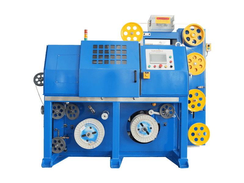
Once individual fibers or fiber-filled tubes are ready, they are stranded around a central strength member, usually a fiberglass reinforced plastic rod or a steel wire, depending on how much tensile load the finished cable needs to survive during installation and how much metal-free construction the application requires.
Most production lines use SZ stranding, where the fibers are wound first in one direction and then reversed in a controlled oscillating pattern. This back-and-forth lay allows individual fibers or tubes to be accessed at any point along the cable without unwinding the entire length, which matters enormously during splicing and repair work in the field. Binder yarns or a wrapping tape hold the stranded bundle together and keep its geometry stable before the next stage begins. Some designs instead use a central loose tube holding all of the fibers together, which simplifies stranding but limits the total fiber count compared to a multi-tube stranded design.
Cable core diameter, roundness, and lay length are all measured continuously during stranding, since any of these three going out of tolerance will show up later as an uneven jacket wall once the core reaches the extrusion stage.
| Strength Member | Typical Use | Key Advantage |
|---|---|---|
| Fiberglass reinforced plastic rod | Aerial and duct cable | Lightweight and fully dielectric |
| Steel wire | Direct burial cable | Higher tensile and crush resistance |
| Aramid yarn | Indoor and patch cable | Flexible with good pull strength |
Armoring: Adding Rodent and Crush Protection
Cable destined for direct burial, or for regions where rodent damage is a known risk, gets an additional armor layer between the stranded core and the outer jacket. The most common approach longitudinally wraps a corrugated steel or aluminum tape around the core, forming it into a snug tube shape before the jacket is extruded over the top.
This armoring step happens in-line, immediately before the core reaches the extruder, using a forming device that folds the metal tape into shape and overlaps its edges to fully enclose the core. Getting the overlap and forming radius right matters: too tight a forming radius can nick the fibers inside, while too loose an overlap leaves a gap that undermines the whole point of the armor. Some designs use two corrugated tapes, one steel and one bonded with a copolymer coating, to combine mechanical protection with a moisture barrier in a single pass.
- Corrugated steel tape armor for maximum crush and rodent resistance
- Aluminum polymer laminate armor where a fully dielectric design is not required but weight matters
- Aramid or glass yarn wraps used instead of metal armor for fully dielectric, lightning-safe designs
Jacketing and Sheathing: Where Extrusion Technology Takes Over
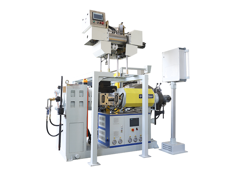
The final stage of cable production is jacketing, and this is the point where a wire and cable sheath extrusion machine does the heaviest lifting on the entire line. The assembled fiber core is fed through a payoff device, any required steel or aluminum armor tape is wrapped and formed around it, and the core then passes through a crosshead die on the extruder, where molten polymer is applied evenly around the full circumference.
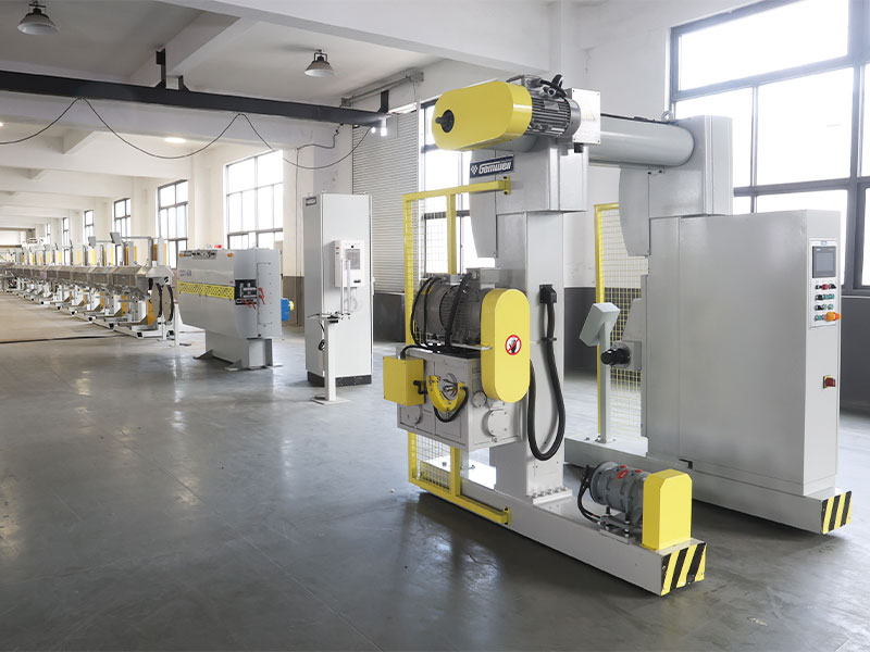
A typical wire and cable sheath extrusion machine used for optical cable includes a feeding and drying unit for the resin, a screw and barrel assembly that melts and pressurizes the polymer, a 90-degree or in-line extrusion head, a water cooling trough immediately downstream, a spark tester, and a belt or capstan haul-off that pulls the cable through the line at a controlled, constant speed. Line speed and cooling rate have to be matched precisely, because a jacket that cools too quickly can shrink unevenly, while one that cools too slowly can deform under its own weight before it sets.
Modern extrusion lines used for this stage commonly run outer diameters from about 3 millimeters up to 90 millimeters or more, depending on whether the target product is a small indoor drop cable or a large-diameter duct or armored cable, with line speeds ranging anywhere from around 20 meters per minute for thick, armored jackets up to well over 100 meters per minute for thin-walled indoor cable.
Inside a Wire and Cable Sheath Extrusion Machine
Understanding the individual components of a wire and cable sheath extrusion machine makes it much easier to diagnose a jacketing problem or to compare two competing machine quotes on equal terms. Every extruder is built around a screw turning inside a heated barrel, but the details of that screw and barrel design have a direct effect on melt quality and, ultimately, on how consistent the finished jacket will be.
Screw design
Barrel diameters for optical cable jacketing commonly range from around 45 millimeters up to 120 millimeters, with an L to D ratio, the barrel length divided by its diameter, typically between 24 to 1 and 30 to 1 to give the resin enough dwell time to melt evenly.
Heating zones
The barrel is divided into multiple independently controlled heating zones, so the resin can be brought up to melt temperature gradually rather than all at once, reducing the risk of degraded or unevenly melted polymer.
Crosshead die
The crosshead redirects the melt flow ninety degrees around the moving cable core, and its internal geometry has to be centered precisely to avoid an eccentric, unevenly thick jacket wall.
Cooling trough
A multi-stage water trough, sometimes with separate warm and cold sections, sets the final jacket dimensions and surface finish as the cable exits the die.
Downstream of the extruder itself, a diameter gauge, usually a laser-based non-contact sensor, feeds data back to the haul-off and extruder controls in a closed loop, automatically nudging screw speed or line speed to hold the outer diameter within a tight tolerance band without an operator intervening on every meter of cable produced.
Comparing Fiber Optic Cable Sheath Materials
The polymer chosen for the outer sheath has a direct effect on where a cable can be installed and how long it will last there. The table below compares the materials most commonly run through a wire and cable sheath extrusion machine in optical cable production.
| Material | Best Suited For | Notable Trait |
|---|---|---|
| Polyethylene (PE) | Outdoor, direct burial, duct | Strong moisture and UV resistance |
| PVC | General indoor cable | Cost effective and flexible |
| Low smoke zero halogen (LSZH) | Indoor risers, plenum spaces | Low toxic smoke output when heated |
| Medium density polyethylene (MDPE) | Aerial and figure-8 self-supporting cable | Balance of flexibility and toughness |
| Polyurethane | Rugged, flexing, or tactical field cable | High abrasion and flex-fatigue resistance |
Resin selection is not purely about the finished cable's environment either. Some polymers process at a narrower melt temperature window than others, which changes how forgiving a given wire and cable sheath extrusion machine needs to be in its temperature control system. LSZH compounds in particular tend to be more sensitive to overheating than standard PE, since scorched LSZH resin loses some of its flame-retardant performance.
What to Look For When Choosing an Extrusion Line for Optical Cable
Buyers evaluating a wire and cable sheath extrusion machine for optical cable production tend to focus on price and headline speed first, but a handful of less obvious specifications usually matter more for long-term output quality.
- Screw and barrel wear resistance, since abrasive, filled compounds like LSZH degrade a standard steel barrel far faster than plain PE
- Closed-loop diameter control, so the line adjusts itself in real time instead of relying purely on operator monitoring
- Number and independence of heating zones, which affects how well the line handles temperature-sensitive resins
- Cooling trough length and stage count, since undersized cooling is one of the most common bottlenecks on high-speed lines
- Compatibility with existing payoff, armoring, and take-up equipment already installed on the factory floor
A line that runs fast on paper but cannot hold tight diameter tolerance on a temperature-sensitive compound will end up producing more scrap, not more usable cable, once it is put into daily production.
Automation and In-Line Monitoring on Modern Production Lines
Newer optical cable lines increasingly tie every stage, from stranding through jacketing, into a single control system rather than running each machine independently. Line speed, tension, and temperature data from the extruder can be logged automatically and cross-referenced against the finished cable's later test results, which makes it far easier to trace a defect back to the exact production run and machine setting that caused it.
Laser diameter gauges, spark testers that check jacket integrity at high voltage as the cable moves, and automatic length counters are now standard on most mid-to-large production lines, replacing manual spot checks that used to happen only a few times per shift. Continuous, automated monitoring catches a drifting parameter within seconds rather than after an entire reel has already been produced out of tolerance, which is one of the biggest quality improvements the industry has made in recent years.
Quality Testing Before the Cable Ships
Finished cable does not leave the factory floor until it passes a series of physical and optical checks. These tests confirm that every stage of the process, from preform to jacket, was executed within tolerance.
- Attenuation testing, which measures how much signal strength is lost per kilometer of fiber
- Tensile strength testing, pulling the finished cable to confirm it can survive installation loads
- Crush and impact testing, simulating the mechanical stress of burial or conduit installation
- Temperature cycling, checking the jacket and buffer for cracking across extreme heat and cold
- Water penetration testing, confirming the gel or dry blocking material stops moisture migration
- Spark testing the jacket at high voltage to catch pinholes or thin spots left over from extrusion
A cable that passes attenuation testing but fails a crush or bend test is still not field ready, since real installations subject cable to mechanical stress far more often than to pure optical strain. Reels are also sampled and cross-checked against the production log for that batch, so any deviation flagged during testing can be traced back to a specific stranding, armoring, or extrusion run rather than treated as an isolated, unexplained failure.
Common Manufacturing Defects and How They Are Prevented
Most optical cable failures can be traced back to a small handful of process variables. Understanding them helps buyers ask sharper questions when evaluating a production line or a finished cable batch.
| Defect | Root Cause | Prevention |
|---|---|---|
| Uneven jacket wall thickness | Inconsistent extruder screw speed or die centering | Laser diameter gauging with automatic feedback control |
| High attenuation spots | Micro-bending during stranding or excessive fiber tension | Controlled fiber excess length and tension monitoring |
| Water ingress over time | Incomplete gel filling or gaps in blocking tape | Precision grease filling equipment and post-fill inspection |
| Jacket surface pinholes | Moisture in resin or contaminated feed material | Resin drying before feeding and inline spark testing |
| Cable stiffness or cracking in cold weather | Wrong jacket resin chosen for the climate zone | Matching resin low-temperature rating to the deployment region |
Frequently Asked Questions
What is fiber optic cable made of
The core and cladding are made of ultra-pure doped silica glass. The fiber is then protected with an acrylate coating, a buffer layer, a strength member such as fiberglass rod or aramid yarn, and an outer polymer jacket such as polyethylene, PVC, or low smoke zero halogen compound.
How thin is an optical fiber compared to a human hair
A standard optical fiber core and cladding together measure about 125 microns in diameter, which is roughly the same thickness as an average human hair, even though the finished cable around it can be many times larger once buffering, strength members, and the jacket are added.
Why does the jacketing stage need a dedicated extrusion machine
The jacket has to be applied around the finished fiber core in a single continuous pass, at a controlled temperature and line speed, without touching or compressing the fibers inside. A purpose-built wire and cable sheath extrusion machine is designed specifically to melt, apply, and cool that polymer layer evenly around a moving cable core.
What is the difference between tight-buffered and loose-tube fiber
Tight-buffered fiber has a thick polymer layer extruded directly onto the coated fiber, which makes it easier to handle indoors. Loose-tube fiber sits inside a gel-filled or dry tube with room to move, which better absorbs temperature-driven expansion and contraction over long outdoor spans.
How is the quality of a finished cable verified
Finished cable goes through attenuation testing, tensile and crush testing, temperature cycling, spark testing, and water penetration testing before it is approved for shipment, confirming that every stage from preform to jacket met specification.
Why do single-mode and multi-mode fiber require different manufacturing precision
Single-mode fiber uses a much smaller core, around 9 microns, which demands a far more precise doping gradient during preform fabrication than the larger 50 or 62.5 micron core used in multi-mode fiber.
How fast does a cable jacketing line typically run
Line speeds vary widely by jacket thickness and diameter, ranging from around 20 meters per minute for thick, armored outdoor jackets up to well over 100 meters per minute for thin-walled indoor cable.
What causes uneven wall thickness in a cable jacket
Uneven jacket walls most often come from inconsistent extruder screw speed or a poorly centered crosshead die, which is why closed-loop laser diameter gauging tied back to the extruder controls has become standard on modern production lines.
 Related Products