E-mail: info@gem-cablesolution.com
 Address: No.8 Yuefeng Rd, High Tech Zone, Dongtai, Jiangsu, China | No.109 Qilin East Rd, Daning, Humen, Dongguan, Guangdong, China.
 English
  English
 русский
 日本語
日本語 Español
 عربى
عربى 中文简体
中文简体



Content
- 1 The Direct Answer: What Defines A Good Copper Wire Stranding Cross Section Machine
- 2 A Short History Of How Stranding Equipment Evolved
- 3 Core Working Principle Behind Stranding And Twisting
- 4 Four Machine Families Compared Side By Side
- 5 Cross Section Geometry: Lay Length, Layer Pattern, And Compaction
- 6 Where A Wire Pair Twisting Machine Fits Into The Line
- 7 Copper Grade, Drawing, And Annealing Effects On Stranding Quality
- 8 Tension Control Systems And Why They Matter More Than Motor Power
- 9 In-Line Quality Checks Operators Run During A Production Shift
- 10 Common Cross Section Defects And Their Root Causes
- 11 Automation, PLC Control, And Data Logging On Modern Lines
- 12 Industry Applications For Stranded And Twisted Copper Conductors
- 13 Energy Consumption And Line Efficiency Considerations
- 14 Maintenance Habits That Keep Cross Section Accuracy Stable
- 15 Choosing Between Machine Types For A New Production Line
- 16 Frequently Asked Questions
- 16.1 What cross section tolerance should a copper stranding machine hold?
- 16.2 Is a wire pair twisting machine the same as a strand bunching machine?
- 16.3 Why does compaction change the outer diameter of a stranded conductor?
- 16.4 What causes an oval instead of round cross section after stranding?
- 16.5 How often should forming dies be replaced on a stranding line?
- 16.6 Why does twist pitch differ between pairs inside the same multi-pair cable?
- 16.7 What is the difference between a friction brake and a magnetic particle brake?
The Direct Answer: What Defines A Good Copper Wire Stranding Cross Section Machine
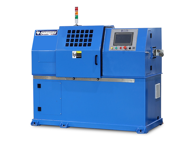
A copper wire stranding cross section machine is judged first by dimensional repeatability, not by top speed. The direct benchmark used across most conductor factories is a finished cross-sectional area held within plus or minus 1 percent of nominal across an entire production spool, confirmed by continuous laser diameter gauging rather than periodic hand measurement. Everything else in this article, from cage design to die wear schedules, exists to protect that single number.
Stranded copper construction is preferred over solid rod wherever a cable needs to survive repeated bending. Splitting one large conductor into 7, 19, or 37 finer strands distributes bending stress across many small radii instead of one large one, which is the mechanical reason stranded conductors resist fatigue cracking far longer than solid wire of the same cross-sectional area.
A Short History Of How Stranding Equipment Evolved
Early wire stranding relied on simple rope-making frames adapted from textile machinery, where bobbins were mounted on a manually rotated basket. Copper strands were laid together at low speed, and cross section consistency depended heavily on the operator's feel for tension rather than any measured feedback.
The shift to powered rigid frame cages in the mid-twentieth century allowed multiple bobbins to rotate as one balanced unit, which is what first made a genuinely round, repeatable cross section achievable at production speed. Tubular and planetary designs followed once bearing and motor technology matured enough to support higher rotational speeds without excessive vibration.
Modern lines add servo-driven tension control and inline laser gauging, closing the loop between what the machine is doing and what the finished cross section actually measures, second by second, rather than relying on end-of-run sampling.
Core Working Principle Behind Stranding And Twisting
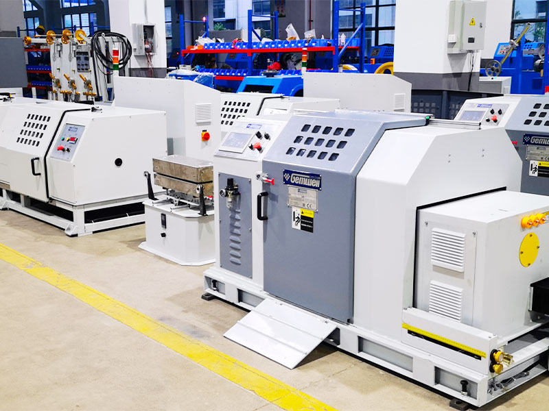
Regardless of machine family, three physical actions happen in sequence: strands are drawn off supply bobbins under controlled back tension, they converge at a forming die or twisting point where the lay geometry is set, and the finished bundle is pulled forward by a capstan at a speed matched to the rotational speed of the twisting element. The ratio between capstan speed and rotational speed is what determines lay length, and lay length is what determines both flexibility and the final packing density of the cross section.
Back tension deserves particular attention because it acts on every single strand independently. If one bobbin brake is even slightly tighter than its neighbors, that strand will sit under more tension than the rest, pulling itself toward the center of the bundle and distorting the outer layer into an irregular, non-round shape once the conductor is finished.
Four Machine Families Compared Side By Side
Bunching Machines
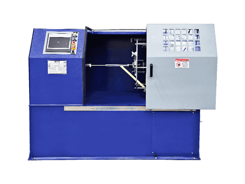
Bunching machines twist a loose group of fine strands, typically between 0.05mm and 0.4mm in diameter, without a rigid bobbin cage carrying the full assembly. This design suits flexible conductors used in earphone cable, USB cable, and thin control wiring, running rotational speeds commonly between 2,000 and 6,000 rpm depending on how many strands are being combined.
Rigid Frame Stranding Machines
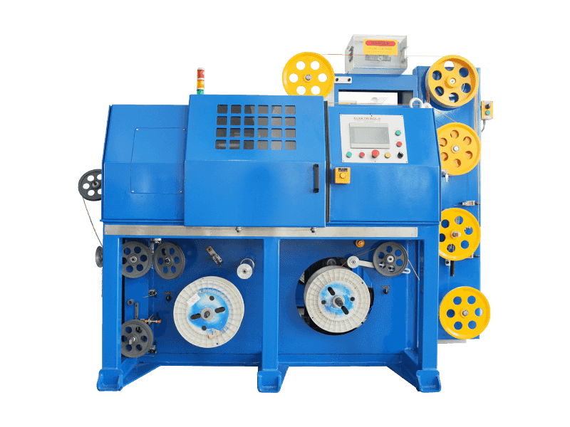
Rigid frame machines mount individual bobbins on a cage that rotates as a single balanced unit, which keeps tension even across every strand. This makes rigid frame equipment the standard choice for medium and large conductors, from around 6 sq mm up to several hundred sq mm, where a round outer layer really matters for downstream extrusion.
Tubular Stranding Machines
Tubular designs pass wire through a rotating tube instead of a full cage frame, cutting down on rotating mass and allowing higher line speed for small and medium sections. Factories running high volume, moderate gauge conductors often prefer tubular equipment for the lower noise and smaller floor footprint.
Planetary Stranding Machines
Planetary machines are built so pre-twisted strands never rotate around their own axis while still being laid together as a bundle. This is the preferred method wherever wire fatigue life outweighs raw production speed, such as power cable cores destined for constant flexing service.
Cross Section Geometry: Lay Length, Layer Pattern, And Compaction
Lay length is the distance along the finished conductor needed for a single strand to complete one full 360 degree wrap. A shorter lay length gives better flexibility but consumes more copper length to cover the same run length, which slightly reduces the effective cross-sectional area if the strand diameter is not adjusted to compensate.
| Layer Structure | Total Strand Count | Common Use |
|---|---|---|
| 1 center + 6 | 7 | Control cable, appliance wiring |
| 1 center + 6 + 12 | 19 | Power distribution cable |
| 1 center + 6 + 12 + 18 | 37 | Flexible welding cable, robotics |
| Multi-layer, 61 strands | 61 | Heavy duty flexible power cable |
Compaction rollers installed directly after the twisting head press the round bundle into a denser profile, removing air gaps between individual strands. A compacted 19-strand conductor typically shows an outer diameter reduction of around 8 to 10 percent compared with the same cross-sectional area left uncompacted, which matters wherever the finished cable has to fit inside a fixed connector barrel or conduit sizing.
Where A Wire Pair Twisting Machine Fits Into The Line
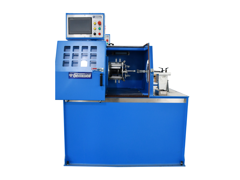
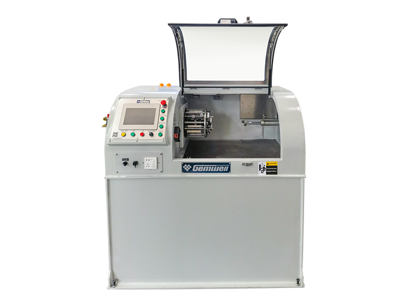
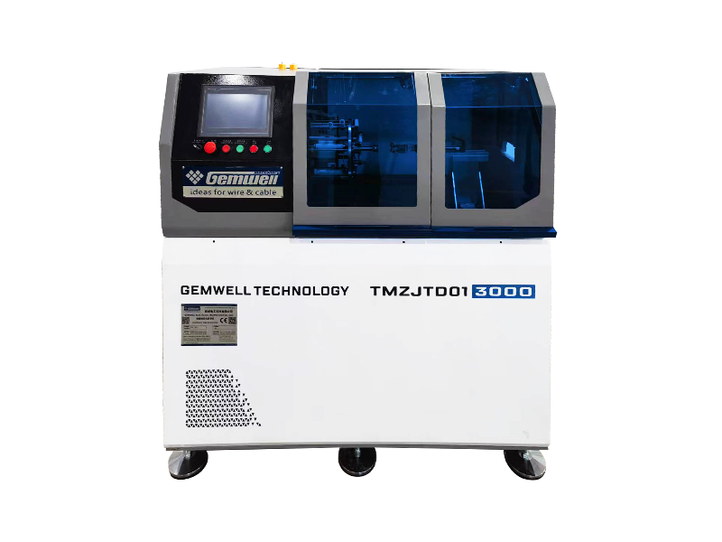
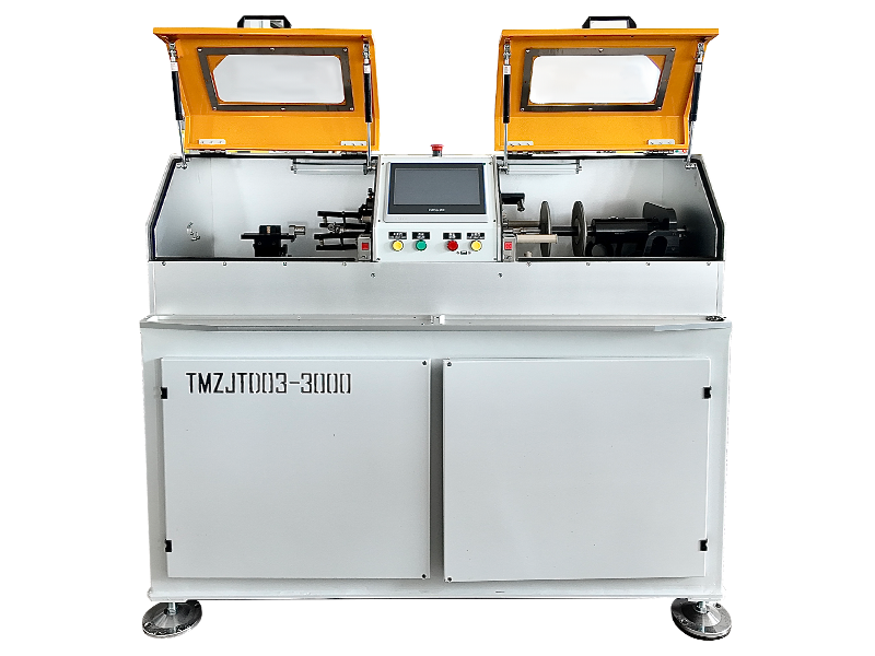
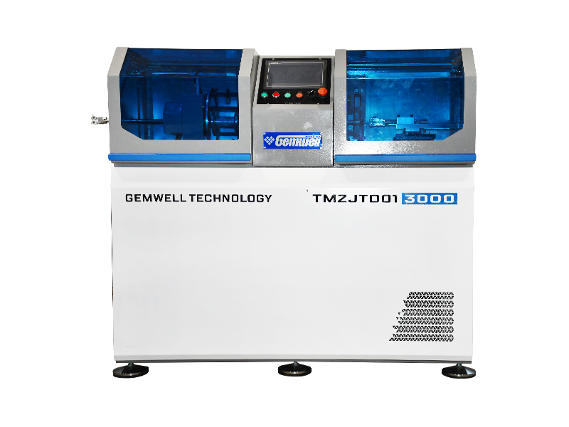
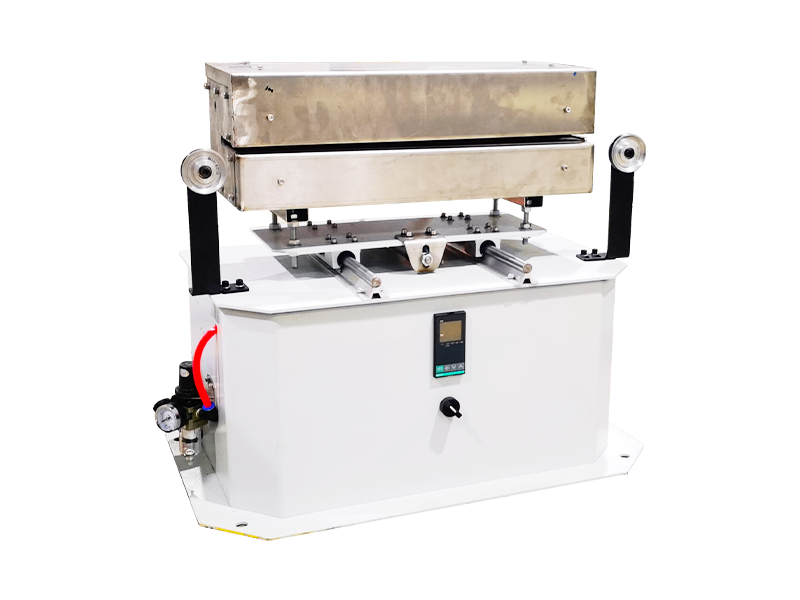
A Wire Pair Twisting Machine is a separate category of equipment from a stranding cross section machine. Instead of combining many bare copper filaments into one conductor, it takes two already-insulated single conductors and twists them around each other to form a balanced pair, the fundamental building block of most data and communication cable. The twist cancels electromagnetic interference between the two conductors, which is the reason every category-rated Ethernet cable and most instrumentation cable relies on twisted pairs rather than a simple parallel lay.
Twist pitch is the parameter engineers track most closely on a wire pair twisting machine. A tighter pitch, meaning more twists per meter, improves noise rejection but consumes more insulated wire per finished meter and slightly increases attenuation at higher frequency. Standard telecom pair production commonly runs a pitch between 12mm and 20mm, and inside a four-pair cable each pair is usually set to a slightly different pitch to avoid crosstalk between neighboring pairs.
Key Adjustable Settings On A Wire Pair Twisting Machine
- Twist pitch, set independently for each spindle position
- Back tension on each individual conductor feed
- Capstan take-up speed, matched precisely to twisting head rpm
- Payoff brake tension to prevent snarling on the supply reel
- Pair-to-pair pitch offset within a multi-pair cable assembly
Many production facilities now combine a copper wire stranding cross section machine for the conductor stage with a wire pair twisting machine for the cabling stage on one continuous line. This reduces handling time between processes and lowers the chance of surface oxidation on bare copper strands left waiting between separate stations.
Copper Grade, Drawing, And Annealing Effects On Stranding Quality
The copper rod feeding a stranding cross section machine is almost always electrolytic tough pitch copper with a purity of 99.9 percent or higher, reduced through a series of drawing dies before it ever reaches the twisting head. Annealing temperature during the drawing stage directly affects how each strand behaves once it hits the stranding cage; under-annealed copper stays stiffer and springs back after the twist, distorting a round cross section into a slightly oval shape once the conductor leaves the forming die.
Conductivity testing after stranding typically targets a value close to 100 percent IACS (International Annealed Copper Standard). Any measured drop below roughly 98 percent IACS usually points to either an overheated drawing die or excessive strand elongation introduced during the stranding pass itself, both of which are worth checking before assuming a raw material quality issue.
Surface finish also plays a role that is easy to overlook. Strands drawn with worn dies pick up fine longitudinal scoring that increases surface resistance slightly and can accelerate localized wear on the stranding machine's forming die once the abrasive strand starts passing through it thousands of times per shift.
Tension Control Systems And Why They Matter More Than Motor Power
Buyers new to stranding equipment often focus on motor horsepower first, but tension control is what actually determines cross section consistency. Mechanical friction brakes were the traditional method, using a spring-loaded pad against each bobbin flange, and while inexpensive, they wear unevenly over time and require frequent manual adjustment to stay balanced across a full bobbin set.
Magnetic particle brakes replaced friction pads on most mid-range and premium machines because they hold a set tension value regardless of how much wire remains on the bobbin, which friction brakes cannot do as the bobbin diameter shrinks during a run. Servo-driven active tension control goes a step further, using a small motor on each bobbin position to actively add or remove tension based on real-time feedback, which is now common on lines producing tight-tolerance cross sections for automotive or aerospace harness applications.
In-Line Quality Checks Operators Run During A Production Shift
Most modern lines fit a laser micrometer directly after the stranding head to record outer diameter continuously rather than relying on hand sampling every few minutes. This catches drift in cross section before an entire spool is affected. Typical checkpoints during a shift include the following.
- Outer diameter measurement, logged continuously by laser gauge
- Lay length verification using a marked strand and a physical ruler check
- Visual inspection of strand surface for scoring marks left by worn dies
- Resistance sampling per 500 meter section against the target ohm per km value
- Spool tension check to confirm even winding without bird-nesting
A sudden change in lay length partway through a spool almost always traces back to a slipping capstan belt or an uneven payoff tension on one of the bobbins, both quick fixes once flagged early rather than discovered after the spool has already been wound and shipped to a customer.
Common Cross Section Defects And Their Root Causes
| Observed Defect | Likely Root Cause | Typical Fix |
|---|---|---|
| Oval cross section | Uneven bobbin back tension | Rebalance brake settings across cage |
| Loose, fuzzy strand lay | Worn forming die | Replace die on scheduled hours |
| Diameter drifting mid-spool | Slipping capstan belt | Retension or replace belt |
| Surface scoring on strands | Worn drawing die upstream | Inspect and swap drawing die set |
| Inconsistent twist pitch on pairs | Worn spindle bearing causing vibration | Lubricate or replace bearing |
Automation, PLC Control, And Data Logging On Modern Lines
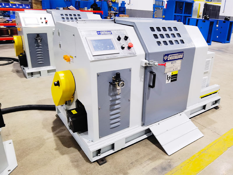
Newer copper wire stranding cross section machine installations run under a programmable logic controller that stores a recipe for each product code, covering lay length, tension setpoints, and capstan speed together in one file. Switching between products becomes a matter of loading a stored recipe rather than manually resetting a dozen dials, which cuts changeover time and reduces the chance of a setup error carrying through an entire run.
Data logging tied to the PLC also creates a traceable record for every spool produced, tagging diameter readings, running speed, and any alarm events against a spool serial number. This traceability becomes valuable whenever a downstream customer reports an issue, since the production team can pull the exact log for that spool rather than relying on memory or a paper logbook.
Industry Applications For Stranded And Twisted Copper Conductors
Stranded copper conductors and twisted pairs show up across a wide span of industries, and each application places a different priority on the cross section machine's output.
| Industry | Priority | Typical Cross Section |
|---|---|---|
| Automotive harness | Flex fatigue resistance | 0.35 to 6 sq mm |
| Data and telecom cable | Consistent twist pitch | 24 to 26 AWG per conductor |
| Building power cable | Round, compacted profile | 6 to 240 sq mm |
| Robotics and drag chain cable | High flex cycle life | 0.14 to 2.5 sq mm |
| Renewable energy cable | High conductivity, weather resistance | 4 to 95 sq mm |
Energy Consumption And Line Efficiency Considerations
Rotating mass is the single biggest driver of energy consumption on a stranding line, since accelerating and decelerating a loaded bobbin cage takes far more power than simply pulling wire forward at constant speed. Tubular designs, which carry less rotating mass than a full rigid frame cage, generally consume noticeably less power per kilogram of finished conductor at comparable output rates.
Variable frequency drives on capstan and cage motors allow a line to ramp speed gradually rather than jumping straight to full rpm, which both protects mechanical components and smooths out the power draw spikes that otherwise show up on a facility's electrical demand charges.
Maintenance Habits That Keep Cross Section Accuracy Stable
Cross section drift on a stranding machine is rarely caused by one dramatic failure; it is usually the slow accumulation of small wear points. Die wear is the most common culprit, since a worn forming die gradually lets the strand bundle open up slightly wider than spec. Operators who log die-hours and replace forming dies on a fixed schedule, rather than waiting for a visible defect, report far fewer out-of-tolerance spools over a full production year.
Bearing lubrication on the rotating cage or tube also affects cross section indirectly. A dry or worn bearing introduces vibration into the twisting head, which shows up as inconsistent lay length rather than a diameter problem, so a technician chasing a diameter complaint should still check bearing condition even when the diameter reading itself looks steady on the log.
Guide roller alignment is another item worth a periodic check, since a slightly misaligned guide roller can introduce a subtle sideways pull on the strand path that shows up later as an oval cross section only under close inspection.
Choosing Between Machine Types For A New Production Line
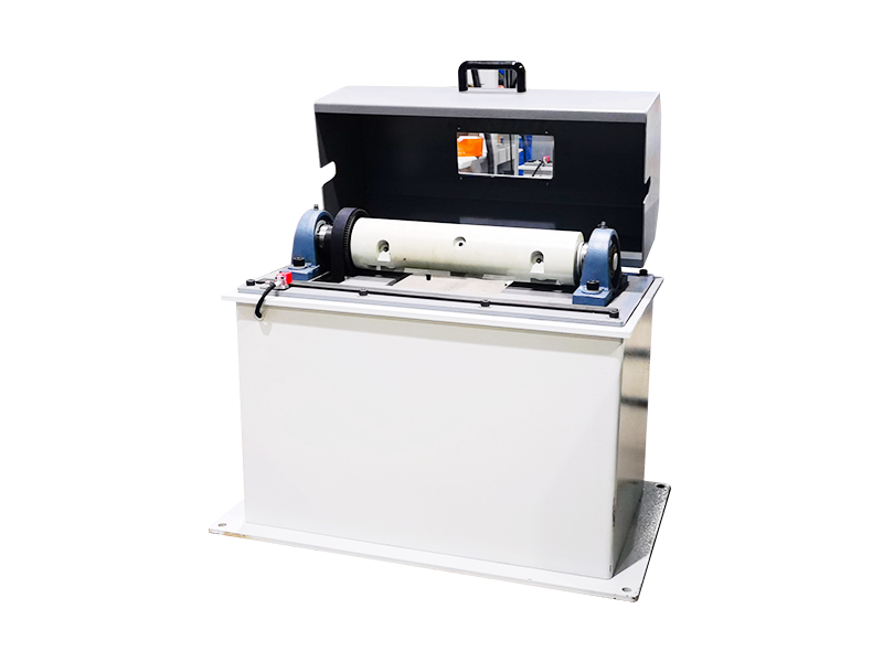
Buyers comparing a copper wire stranding cross section machine against a bunching machine or a wire pair twisting machine should start with the finished product specification, not the equipment catalog. If the output is a single conductor of 6 sq mm or larger destined for power distribution, a rigid frame or tubular strander fitted with compaction rollers is the practical choice. If the output is a two-conductor communication pair, a dedicated wire pair twisting machine with independently programmable pitch per spindle is required, since a stranding machine alone cannot produce a controlled twisted pair from pre-insulated wire.
Line speed compatibility between upstream and downstream equipment also deserves attention. A stranding head running faster than the downstream insulation extruder can handle simply creates a buffer loop problem, so matching capstan speeds across the whole line prevents unnecessary tension spikes that distort cross section at the joint between machines.
Floor space and future product range are worth factoring in early as well. A tubular machine's smaller footprint suits facilities running high volumes of a narrow gauge range, while a rigid frame line offers more flexibility to handle a wider spread of cross sections on the same equipment over time.
Frequently Asked Questions
What cross section tolerance should a copper stranding machine hold?
Most conductor buyers specify a tolerance around plus or minus 1 percent of the nominal cross-sectional area, verified by continuous laser diameter gauging during production rather than spot checks alone.
Is a wire pair twisting machine the same as a strand bunching machine?
No. A bunching machine twists many bare strands into one conductor, while a wire pair twisting machine twists two already-insulated conductors together to form a balanced pair used in data and telecom cable.
Why does compaction change the outer diameter of a stranded conductor?
Compaction rollers press the round strand bundle into a denser shape immediately after twisting, removing air gaps between strands. This typically reduces outer diameter by around 8 to 10 percent compared to an uncompacted bundle of the same cross-sectional area.
What causes an oval instead of round cross section after stranding?
Uneven back tension across bobbins, under-annealed copper springing back after the twist, or a worn forming die are the three most common causes of an out-of-round finished cross section.
How often should forming dies be replaced on a stranding line?
A fixed die-hour replacement schedule, rather than waiting for a visible defect, keeps cross section tolerance stable and avoids the gradual widening that comes with worn dies.
Why does twist pitch differ between pairs inside the same multi-pair cable?
Giving each pair a slightly different pitch reduces the chance that two pairs will pick up interference from each other, since matching pitches between neighboring pairs increases the risk of crosstalk at certain frequencies.
What is the difference between a friction brake and a magnetic particle brake?
A friction brake uses a spring-loaded pad against the bobbin flange and needs manual readjustment as the bobbin empties, while a magnetic particle brake holds a set tension value automatically regardless of remaining wire on the bobbin.
 Related Products