E-mail: info@gem-cablesolution.com
 Address: No.8 Yuefeng Rd, High Tech Zone, Dongtai, Jiangsu, China | No.109 Qilin East Rd, Daning, Humen, Dongguan, Guangdong, China.
 English
  English
 русский
 日本語
日本語 Español
 عربى
عربى 中文简体
中文简体
Content
- 1 Wire Manufacturing at a Glance: From Raw Ore to Finished Cable
- 2 Raw Material Extraction: Where Wire Manufacturing Actually Begins
- 3 Wire Drawing: Precision Reduction to Target Gauge
- 4 Annealing: Restoring Ductility After Cold Working
- 5 Stranding: Building Flexible Multi-Wire Conductors
- 6 The Wire and Cable Extruder: How Insulation Is Applied
- 7 Types of Wire and Cable Extruder Configurations
- 8 Insulation Materials Processed on a Wire and Cable Extruder
- 9 Cabling, Shielding, and Outer Jacket Extrusion
- 10 How to Select the Right Wire and Cable Extruder for Your Production Line
- 11 Quality Control at Every Stage of Wire Manufacturing
Wire Manufacturing at a Glance: From Raw Ore to Finished Cable
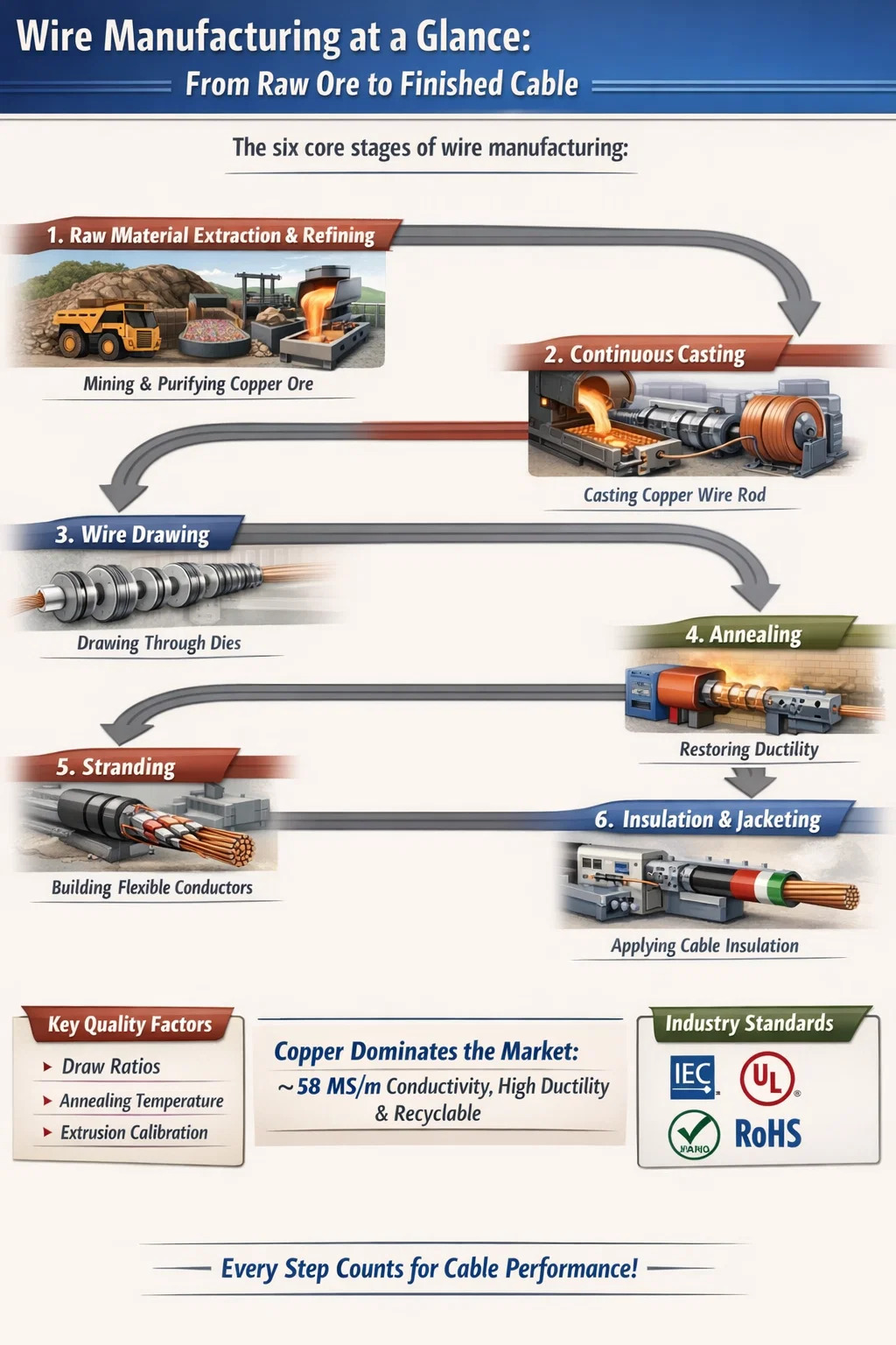
Wire is manufactured through a sequence of six core stages: raw material extraction and refining, continuous casting into wire rod, wire drawing through progressive dies, annealing to restore ductility, stranding to build flexible conductors, and insulation or jacketing via a wire and cable extruder. Every step feeds directly into the next, and a deficiency at any point — wrong draw reduction ratio, incorrect annealing temperature, or a miscalibrated extrusion line — degrades the finished product's electrical performance, mechanical durability, or compliance with standards like IEC 60228, UL, or RoHS.
Copper dominates the market because it combines an electrical conductivity of approximately 58 MS/m at 20°C, excellent ductility, and full recyclability. Aluminum, at roughly 61% of copper's conductivity per unit volume but only 30% of its weight, serves overhead transmission lines where weight savings justify the trade-off. Understanding the mechanics behind each manufacturing stage helps engineers specify cable more precisely, helps procurement teams evaluate suppliers more rigorously, and helps anyone selecting a wire and cable extruder understand what machine specifications actually mean for cable quality.
Raw Material Extraction: Where Wire Manufacturing Actually Begins
Wire manufacturing begins deep underground. Copper ore is recovered from open-pit or underground mines concentrated in South America, Asia, and parts of the United States — the U.S. currently ranks as the fourth-largest copper producer globally, with active mining operations spread across approximately eight states. Raw ore contains only a small proportion of copper mineral; the vast surrounding material, called gangue, must be removed before the metal is usable.
Froth Flotation and Electrolytic Refining
The first separation step is froth flotation. Crushed ore is ground to a fine powder, mixed with water into a mineral pulp, and treated with chemical reagents that cause copper minerals to adhere to rising air bubbles. The floating copper-rich froth is skimmed off and concentrated. What remains after smelting is blister copper — approximately 98–99% pure — which still contains trace impurities that would lower electrical conductivity if left in place.
Electrolytic refining eliminates those impurities. Blister copper anodes are suspended in a copper sulfate solution; an electrical current causes pure copper to dissolve from the anode and deposit with 99.99%+ purity onto cathode blanks. Even trace contaminants like arsenic or bismuth at concentrations above 0.001% measurably reduce conductivity, making this refining step non-negotiable for wire grade copper. The resulting cathode copper is the feedstock for the casting furnace.
Continuous Casting into Wire Rod
Cathode copper is melted in a shaft furnace or induction furnace and continuously cast into wire rod — a round bar that is the universal starting point for wire drawing. The standard diameter for wire rod is 8 mm, and coils are wound to weights of up to 5 tonnes each to allow long, uninterrupted drawing runs. The 8 mm dimension is deliberate: it is large enough to be handled efficiently in casting but small enough to enter the first drawing machine without an intermediate rolling step in most operations. Aluminum rod for electrical conductor use is cast similarly, though aluminum's lower melting point (660°C vs. copper's 1,085°C) and different oxidation behavior require process adjustments at the furnace and in the casting wheel design.
Wire Drawing: Precision Reduction to Target Gauge
Wire drawing transforms the 8 mm rod into wire of the precise diameter specified for a given application. The rod is fed into a draw bench and pulled through a series of progressively smaller dies — typically made of polycrystalline diamond (PCD) or natural diamond for fine gauge wire — each one reducing the cross-sectional area by 15–25% per pass. As the diameter shrinks, the wire elongates in proportion; a kilogram of copper can be drawn to a wire with a diameter of 0.05 mm and a length of approximately 57 kilometers.
Drawing Die Design and Lubrication
Each die consists of three zones: an entry cone that guides the incoming wire, a reduction zone where diameter is decreased, and a bearing zone that sets the final diameter. Diamond is the preferred die material because its hardness (10 on the Mohs scale) resists abrasion from the constant metal-on-die contact over billions of meters of production. Without lubrication, friction between the wire surface and the die generates sufficient heat to prematurely work-harden the copper, increasing wire breakage and die wear. Oil-based emulsions or dry soap compounds are applied continuously at the die entry; on high-speed machines drawing wire at up to 32 m/s, these lubricants simultaneously cool the die and the wire surface.
Modern wire drawing machines operate as multi-die systems, drawing wire through several dies in a single pass rather than making one pass per die. This substantially increases throughput and reduces the number of intermediate annealing steps required on the way to fine gauge. The drawing stage is where the fundamental gauge decision is locked in — subsequent processes can adjust surface properties and add insulation, but they cannot change the conductor cross-section.
| Stage Name | Input Diameter | Output Diameter | Typical End Use |
|---|---|---|---|
| Rod breakdown | 8.0 mm | 2.0 mm | Drawing stock for next stage |
| Intermediate drawing | 2.0 mm | 0.5–1.0 mm | Power cable stranding stock |
| Fine wire drawing | 0.5 mm | 0.05–0.2 mm | Automotive, electronics, telecom |
| Superfine drawing | 0.2 mm | < 0.05 mm | Litz wire, medical devices |
Annealing: Restoring Ductility After Cold Working
Every pass through a drawing die work-hardens copper. The grain structure elongates in the drawing direction, which raises tensile strength but sharply reduces ductility — elongation at break can drop to under 5% after heavy drawing, making the wire prone to fracturing during stranding or installation. Annealing is the heat treatment that reverses this by recrystallizing the metal structure, restoring elongation at break to 25–30% and slightly reducing tensile strength from the work-hardened peak of approximately 400 MPa back to the fully annealed range of 220–250 MPa.
Continuous Inline Annealing vs. Batch Annealing
The preferred approach in modern high-speed wire drawing lines is continuous inline annealing, where an electric current is passed through the wire immediately after the final drawing die, heating it to its recrystallization temperature for a fraction of a second before rapid quenching in water. The entire cycle happens without stopping the line. A critical requirement is preventing oxidation on the hot metal surface; this is handled by feeding the wire through an induction annealing chamber filled with nitrogen or another shielding gas that displaces oxygen, preserving the characteristic bright copper surface. Continuous annealing is the standard method for building wire, automotive wire, and any high-volume application where throughput and consistency matter.
Batch annealing loads coils of drawn wire into electric furnaces under a controlled reducing atmosphere and holds them for 4–8 hours before controlled cooling. It remains applicable for specialty alloys, tinned wire, or production runs too small to justify a dedicated inline annealing machine. The downside is time: while a continuous line anneals wire in milliseconds, a batch cycle measured in hours reduces throughput significantly and requires more handling between steps.
Stranding: Building Flexible Multi-Wire Conductors
A single solid wire of a given cross-section has the lowest manufacturing cost but limited flexibility — it resists bending and accumulates metal fatigue when repeatedly flexed. Stranded conductors twist multiple smaller wires together into a bundle with the same total cross-section, dramatically improving flexibility and fatigue resistance. In IEC 60228 classification, a Class 1 conductor is solid; Classes 2 through 6 represent progressively finer and more numerous strands, with Class 5 and 6 flexible conductors containing dozens of individual wires bundled together for applications that demand repeated flexing — robot cables, portable tools, or automotive harnesses.
Lay Length and Its Effect on Cable Performance
The stranding machine twists individual wires together at a controlled lay length — the axial distance along the conductor over which one strand completes a full 360° helix. Shorter lay lengths produce tighter, more circular bundles with better flexibility and break resistance; longer lay lengths reduce total copper consumption slightly but yield stiffer conductors. For data cables like Cat6, the lay length of each twisted pair is precisely controlled to achieve the specified differential signal delay and crosstalk rejection. An error of even a few millimeters in lay length on a 100-meter Category 6 cable can push it below the 250 MHz performance threshold defined in ISO/IEC 11801. Conductor cross-sections produced on stranding machines range from as small as 0.5 mm² for automotive signal wires up to 400 mm² or beyond for large power cables.
Once stranding is complete, the conductor is ready to enter the wire and cable extruder line for insulation application — the step that transforms bare, functional metal into a safe and durable cable.
The Wire and Cable Extruder: How Insulation Is Applied
The wire and cable extruder is the machine that converts bare conductor into insulated wire by coating it with a precisely dimensioned layer of thermoplastic or thermosetting polymer. It is the single most capital-intensive piece of equipment on a cable production line and the primary determinant of insulation wall thickness consistency, surface quality, and adherence to electrical standards. The wire and cable extruder works on a straightforward principle: solid polymer pellets enter the feed hopper, travel through a heated barrel where a rotating screw melts and pressurizes them, and the resulting viscous melt is forced through a crosshead die that deposits it uniformly around the moving conductor.
The Three Screw Zones and Why They Matter
Every wire and cable extruder screw is divided into three functional zones. The feed zone conveys solid pellets from the hopper into the heated barrel at a controlled rate; the compression zone progressively melts the polymer and purges trapped air; the metering zone pumps a stable, homogeneous melt stream at constant pressure toward the crosshead die. The screw's length-to-diameter (L/D) ratio — typically 24:1 to 30:1 on modern cable extruders — determines how much dwell time the melt has in the barrel. A longer screw provides more thorough melting and mixing, which matters most when processing demanding materials like XLPE or halogen-free flame-retardant (HFFR) compounds with high mineral filler loadings.
The feed throat — where pellets first enter from the hopper — is water-cooled to a controlled temperature. This prevents premature softening of pellets in the throat zone, which would cause bridging: a solid blockage that stops material flow and forces a line shutdown to clear. This detail is often underestimated in wire and cable extruder selection, but an undersized cooling circuit at the feed throat is a reliable cause of unstable output on hot-running materials like LSZH compounds.
The Crosshead Die: Pressure Tooling vs. Tubing Tooling
The crosshead die is the component that guides the bare conductor through the center of the melt stream and shapes the insulation around it. Two tooling configurations exist. Pressure tooling brings the melt into contact with the conductor before the die exit, under pressure, which promotes strong mechanical adhesion between insulation and conductor — preferred for PVC and PE general-purpose cables where insulation stripping force is a quality parameter. Tubing tooling forms the melt into a hollow tube that collapses onto the conductor after the die exit; this approach is preferred for XLPE cables where the melt must exit the die before crosslinking begins in the downstream CV tube, and any contact under pressure would cause premature gelation at the die face and surface defects.
Cooling Trough, Spark Tester, and Capstan
After the die, the insulated wire enters a water-filled cooling trough — typically 3 to 10 meters in length on standard wire and cable extruder lines, longer on heavy power cable lines. Trough water temperature is calibrated to line speed and insulation wall thickness: too cold causes thermal shock stress in thick-wall insulation; too warm leaves the insulation partially soft and prone to deformation under the capstan pull. A high-voltage spark tester positioned inline applies 5–20 kV continuously to the insulated wire surface, detecting pinholes or thin spots that would allow current leakage. Any fault triggers an alarm, and modern lines can automatically mark the defect position on the wire for downstream removal. The capstan maintains constant line tension as the coated wire is wound onto the take-up reel; tension that is too high stretches the insulated wire and reduces outside diameter; too little causes loose, snarled winding.
Types of Wire and Cable Extruder Configurations
Wire and cable extruder designs are not interchangeable. The choice of extruder type determines what materials can be processed, at what throughput, and at what quality level. Matching the extruder type to the cable product is one of the first decisions a production engineer faces when specifying a new insulation line.
Single-Screw Extruder
The single-screw wire and cable extruder is the industry standard for the majority of cable types. It handles PVC, PE, XLPE, nylon, and TPU reliably, with screw diameters ranging from 30 mm to 200 mm depending on required output. A 60 mm machine typically delivers 80–150 kg/h with PVC; a 120 mm machine reaches up to 440 kg/h with PVC and can run line speeds of 3–80 m/min on power cable jacketing applications. For high-speed thin-wire applications such as building wire (BV/BVR) or automotive low-voltage wire, single-screw machines on dedicated lines routinely achieve 500–1,500 m/min. The single-screw design's main limitation is mixing capability: it is adequate for homogeneous compounds but struggles with high-filler blends that require intensive dispersive mixing.
Twin-Screw Extruder
Twin-screw wire and cable extruders use two intermeshing screws that provide far superior mixing compared to a single screw. This design is specifically needed for HFFR compounds, where mineral flame-retardant fillers such as aluminum trihydrate (ATH) or magnesium hydroxide can comprise up to 60% of compound weight. Achieving uniform filler dispersion — critical for the compound to meet oxygen index and UL 94 flame ratings — requires the intensive shear and mixing that only twin-screw geometry provides. The higher capital cost of a twin-screw machine is justified in any operation producing flame-retardant cables for rail transit, data centers, or building wiring projects where LSZH certification is mandatory.
Co-Extrusion Lines: Dual and Triple Layer
Co-extrusion lines connect two or three wire and cable extruder units to a single multi-layer crosshead, depositing multiple insulation or jacket layers simultaneously in one production pass. Dual co-extrusion is common for nylon-over-PVC THHN building wire, where the primary insulation layer and the nylon abrasion-resistant skin are applied in a single operation rather than two separate extruder passes. Triple co-extrusion is the standard configuration for medium-voltage XLPE power cable production, where the inner semiconductive shield, XLPE insulation, and outer semiconductive shield must be applied simultaneously to achieve perfect bonding at both interfaces — a requirement of IEC 60502 and IEEE standards for cables operating above 1 kV. High-performance building wire lines with dual co-extrusion capability can reach line speeds of up to 1,200 m/min for fine gauge wire.
Continuous Vulcanization (CV) Lines for Rubber Cables
Rubber-insulated cables — used in mining, welding, shipbuilding, and high-temperature industrial environments — require a wire and cable extruder connected to a continuous vulcanization tube. After the rubber compound (EPR, silicone, EPDM) exits the extruder die, it passes through a pressurized, heated CV tube where vulcanization crosslinks the rubber into its final state. Steam CV systems operate up to 200°C and are lower in capital cost. Dry nitrogen CV systems operate up to 230°C and provide a faster, more controllable cure — strongly preferred for XLPE medium-voltage cables where any moisture from steam could form micro-voids in the insulation wall that lower partial discharge inception voltage.
| Extruder Type | Primary Materials | Typical Line Speed | Core Strength | Main Application |
|---|---|---|---|---|
| Single-screw | PVC, PE, XLPE, TPU | 200–1,500 m/min | Low cost, wide material range | Building wire, power cable |
| Twin-screw | HFFR, high-fill compounds | 100–400 m/min | Superior dispersive mixing | LSZH, flame-retardant cable |
| Dual co-extrusion | PVC/nylon, XLPE/PE | 200–1,200 m/min | Two layers in one pass | THHN building wire |
| Triple co-extrusion | Semiconductor + XLPE | Up to 1,200 m/min | Perfect interface bonding | Medium-voltage power cable |
| CV rubber line | EPR, EPDM, silicone | 5–80 m/min | Continuous vulcanization | Mining, welding, marine cable |
Insulation Materials Processed on a Wire and Cable Extruder
The insulation compound processed by the wire and cable extruder is not a fixed choice — it depends on the cable's intended application, operating temperature, fire performance requirement, and installation environment. Different materials have fundamentally different melt viscosities, thermal sensitivity, and abrasiveness in the barrel and screw, all of which influence the extruder specification required.
- PVC (Polyvinyl Chloride): The most widely used insulation material for general-purpose building and control wire. Processes well on standard single-screw extruders at barrel temperatures between 160°C and 195°C. Its inherent chlorine content provides natural flame retardancy, but when burned, PVC releases hydrogen chloride gas — which is why PVC has been displaced by LSZH in subway cars, tunnels, and data centers where toxic smoke in an emergency is unacceptable.
- XLPE (Cross-Linked Polyethylene): The standard insulation for medium- and high-voltage power cables and for automotive under-hood wiring operating at 90°C to 125°C continuous. The extruder processes XLPE at 120–140°C — well below the crosslinking activation temperature — and crosslinking occurs downstream in the CV tube or by electron beam irradiation after the extruder. The crosslinked network resists deformation under sustained heat load far better than thermoplastic PE and dramatically improves short-circuit current rating.
- LSZH / HFFR (Low Smoke Zero Halogen / Halogen-Free Flame Retardant): Polyolefin-based compounds loaded with up to 60% by weight of mineral flame-retardant fillers. These fillers make the melt highly viscous and abrasive, demanding wear-resistant bimetallic barrel liners and alloy steel screws on the wire and cable extruder, plus a twin-screw design in many cases to achieve uniform filler dispersion. The payoff is a cable that, when exposed to fire, produces minimal smoke and no corrosive halogen gases — mandatory for EN 50575 CPR classification Dca and above in European building wire.
- Fluoropolymers (FEP, ETFE, PTFE): Used in aerospace wiring, military cables, and high-frequency signal cables requiring continuous service above 200°C or exceptionally thin insulation walls. Fluoropolymer extrusion requires PTFE-lined barrels, compression ratios as low as 1:1, and barrel temperatures up to 380°C. Dedicated Teflon wire and cable extruder lines run at lower speeds than thermoplastic lines, typically 15–210 m/min, but produce cables with performance no other insulation can match — including wall thicknesses down to 0.076 mm at outside diameters of 0.67–4.4 mm for aerospace signal wire.
- TPU (Thermoplastic Polyurethane): Used for high-flex cable jackets on USB cables, robotics cables, and portable power tools where the jacket must survive millions of flex cycles. TPU processes on standard single-screw extruders at 190–210°C and provides excellent abrasion resistance and cold-temperature flexibility down to –40°C. Its higher raw material cost compared to PVC is accepted in applications where jacket durability directly affects product service life.
- Nylon (PA): A thin outer layer of nylon applied over PVC insulation defines the THHN/THWN building wire class dominant in North American construction wiring. The nylon layer, typically 0.076 mm thick, is applied in a co-extrusion pass on the wire and cable extruder line and provides abrasion and heat resistance that qualifies the wire for conduit installation per NEC requirements. A 120 mm co-extrusion extruder line running nylon-over-PVC can reach line speeds of 500 m/min on 12 AWG wire.
Cabling, Shielding, and Outer Jacket Extrusion
Multi-conductor cables require a cabling operation after individual core insulation. The cabling machine lays insulated cores together in a controlled helical pattern, producing a round, mechanically stable bundle ready for final jacketing. For data cables, the precise twist geometry of each core pair determines the cable's signal integrity, crosstalk rejection, and return loss — the cabling step is as much a signal engineering operation as a mechanical one.
Electromagnetic Shielding Layers
Many cables include a metallic shield layer — foil, braid, or combination — between the cabled cores and the outer jacket. An aluminum/polyester foil shield provides 100% coverage and is used in instrument cables, audio cables, and low-frequency signal cables. A tinned copper braid over the foil adds mechanical robustness and lowers transfer impedance, making it the preferred solution for RF coaxial cables, shielded multicore industrial cables, and high-frequency data cables. Braiding machines apply the shield by weaving fine metallic strands across the cable in crossing helical paths; braid coverage of 85–95% is typical for cables specified under IEC 61156 or MIL-C-17.
Steel Wire Armor for Mechanical Protection
Direct-burial cables, mine cables, and submarine cables require armoring against mechanical damage from soil pressure, digging equipment, and marine hazards. Steel wire armor (SWA) is applied in a separate armouring operation, winding galvanized or epoxy-coated steel wires in a helical layer around the cabled assembly over an inner bedding. The armor provides crush resistance and rodent protection while the underlying inner bedding holds the cores together and protects insulation from the steel. Aluminum wire armor (AWA) is used on single-core power cables where steel armor would create eddy current losses in the AC magnetic field.
Final Outer Jacket Extrusion
The last pass through a wire and cable extruder applies the outer jacket — the cable's visible exterior layer and primary environmental barrier. Jacket material is chosen by installation environment: PVC for general indoor use and direct burial (with suitable plasticizer); MDPE or HDPE for underground and submarine cables where moisture permeability must be minimized; LSZH for enclosed public spaces; polychloroprene for cables exposed to UV, oils, and chemicals in outdoor or marine environments. The outer jacket also carries the mandatory cable marking — manufacturer, cable designation, conductor cross-section, construction standard, CE or UL marking, and meter-by-meter length marks — either printed by an inline inkjet printer or embossed in the jacket surface during the extrusion pass itself. Cables are rated for service lives of 40 to 60 years under normal operating conditions, and the outer jacket quality largely determines whether that service life is achieved.
How to Select the Right Wire and Cable Extruder for Your Production Line
The wire and cable extruder is the largest single capital investment on an insulation line and the most direct determinant of cable quality and throughput. Selecting the wrong configuration leads to output inconsistency, elevated scrap rates, and expensive remediation — industry statistics suggest that an application-mismatched extruder can reduce production efficiency by 30% or more compared to a properly matched machine. The following parameters are the decisive evaluation criteria.
- Screw diameter and output rate: Screw diameters for wire and cable extruder machines are available in a wide range — 30 mm, 45 mm, 60 mm, 65 mm, 80 mm, 90 mm, 100 mm, 120 mm, 150 mm, and 200 mm are standard sizes. Select based on required kg/h output at the target line speed for your specific compound. A line running 3 shifts at 250 days per year will accumulate over 18,000 operating hours; even a 10 kg/h output difference translates to hundreds of tonnes of additional production capacity annually.
- L/D ratio: For standard PVC and PE compounds, an L/D of 20:1 to 25:1 is adequate. For XLPE, LSZH, and other thermally sensitive or highly filled compounds, specify 28:1 to 36:1 to ensure sufficient residence time for complete melting and uniform melt temperature — the basis for consistent wall thickness and absence of cold spots that fail the spark tester.
- Barrel and screw metallurgy: Match the material of the screw and barrel to the abrasiveness and corrosivity of your compound. HFFR and mineral-filled compounds are highly abrasive; bimetallic barrels with wear-resistant bore liners and alloy-steel screws are required. PVC at processing temperature is corrosive to standard steel; corrosion-resistant barrel linings are specified for high-PVC output lines. Selecting inadequate metallurgy delivers an apparent capital saving that is rapidly reversed by early barrel wear, dimensional inconsistency, and unplanned maintenance shutdowns.
- Temperature control precision: Premium wire and cable extruder machines maintain individual barrel zone temperatures within ±1°C across a range of 0–380°C. Inadequate temperature control causes melt viscosity fluctuations that directly produce wall thickness variation — the leading cause of spark test failures and dimensional rejects on PVC insulation lines.
- PLC control and recipe management: Modern wire and cable extruder lines are controlled by PLC systems with touchscreen HMIs that store complete process recipes — barrel zone temperatures, screw speed, line speed, cooling trough settings — for every cable SKU in production. For a cable factory running 50 or more product types, the ability to recall a recipe in seconds versus manually re-entering parameters eliminates hours of setup scrap per week and is one of the clearest return-on-investment items in extruder specification.
- Energy efficiency: The wire and cable extruder is the largest power consumer on the extrusion line. Machines with optimized screw geometry, insulated barrels, and variable-frequency drive motors reduce energy consumption per kilogram of output by 15–25% versus older designs. At the scale of a major cable plant running millions of meters annually, this difference has a measurable impact on per-meter production cost and carbon footprint.
- Co-extrusion capability and future product roadmap: If your product pipeline includes multi-layer cable constructions — nylon-over-PVC THHN, dual-layer automotive wire, or medium-voltage XLPE — specify the line architecture to accommodate a secondary or tertiary extruder feeding the same crosshead. Retrofitting co-extrusion onto a single-extruder line not designed for it typically costs more than specifying it from the outset and results in poorer layer interface quality than a purpose-built co-extrusion crosshead.
Quality Control at Every Stage of Wire Manufacturing
Wire manufacturing is a continuous-length process — a defect introduced at any stage propagates through potentially thousands of meters of product before detection if inline monitoring is absent. Quality management is therefore embedded at each step, not reserved for end-of-line inspection.
Inline Dimensional and Electrical Monitoring
Laser-based diameter gauges positioned after the wire and cable extruder die measure outside diameter on 2–4 axes simultaneously at up to 20,000 measurements per axis per second. These non-contact systems detect lumps and neckdowns in real time and feed back to the extruder screw speed and line speed controller, maintaining diameter within ±0.01 mm of the target value across the production run. High-voltage spark testers apply 5–20 kV continuously and detect pinholes down to single-micron scale defects in insulation wall thickness. Eccentricity — the offset of the conductor from the geometric center of the insulation — is measured optically and used to adjust the crosshead die position in real time on automated lines.
Laboratory Testing and Certification Release
Beyond inline checks, production batches are sampled for laboratory testing before release. Conductor resistance is measured per IEC 60228 to confirm cross-section and metal purity. Insulation resistance testing verifies that no leakage current flows through the polymer wall at rated voltage. Mechanical tests — tensile strength, elongation at break, and cold bend at –15°C or –40°C depending on the standard — confirm that the insulation compound was correctly processed and that extrusion temperature did not degrade the polymer. For cables under CPR, UL, or VDE certification, flame propagation tests per IEC 60332-1, IEC 60332-3, or UL 1685 are run on finished cable samples. A failed flame test traces to one of three root causes: incorrect compound, inadequate wall thickness, or extrusion barrel temperature above the decomposition point of the flame-retardant additives — all of which point back to the wire and cable extruder process parameters.
Final Reel-Up, Marking, and Dispatch
Cables that pass all inline and laboratory tests are wound to the specified length, cut, capped, and labeled with construction details, batch number, length, and certification marks. Finished drums are staged for sampling from completed reels — a mandatory step under third-party certification programs — before release to the warehouse. From electrolytic copper cathode to certification-stamped cable drum, the total manufacturing cycle for a standard power cable involves more than a dozen individual process steps, each with its own quality gate. The wire and cable extruder line sits at the center of this chain: everything before it prepares the conductor, and everything after it adds mechanical protection. Getting the extrusion process right is the central task of wire manufacturing.