E-mail: info@gem-cablesolution.com
 Address: No.8 Yuefeng Rd, High Tech Zone, Dongtai, Jiangsu, China | No.109 Qilin East Rd, Daning, Humen, Dongguan, Guangdong, China.
 English
  English
 русский
 日本語
日本語 Español
 عربى
عربى 中文简体
中文简体
Content
- 1 What Is Extrusion — The Core Process Behind Every Wire and Cable
- 2 How a Wire and Cable Extruder Actually Works
- 3 Types of Wire and Cable Extruders by Configuration
- 4 Key Materials Processed on Wire and Cable Extruders
- 5 Critical Parameters That Define Extrusion Quality
- 6 Wire and Cable Extruder Line Layout and Auxiliary Equipment
- 7 Extrusion Defects in Wire and Cable Production and How to Resolve Them
- 8 Selecting a Wire and Cable Extruder for Your Production Requirements
- 9 Extrusion in Specialized Cable Applications
- 10 Maintenance Practices That Extend Wire and Cable Extruder Service Life
- 11 Industry Trends Shaping Wire and Cable Extrusion Today
What Is Extrusion — The Core Process Behind Every Wire and Cable
Extrusion is a continuous manufacturing process in which raw material — typically a thermoplastic or elastomeric compound — is melted and forced through a shaped die to produce a uniform cross-section profile. In the wire and cable industry, this means applying an insulating or jacketing layer directly onto a moving conductor at speeds that can exceed 1,200 meters per minute on high-speed lines for fine-gauge data cables. The result is a consistent coating that protects the conductor, provides electrical insulation, and meets dimensional tolerances down to ±0.01 mm on premium automotive or medical-grade products.
Unlike injection molding — which fills a closed mold and requires cycle time — extrusion is inherently inline and never stops. A wire and cable extruder feeds pellets or powder into a heated barrel, a rotating screw conveys and plasticizes the compound, and the molten material exits through a crosshead die positioned around the conductor. The coated wire then enters a cooling trough, passes through spark testers and diameter gauges, and is wound onto a take-up reel, all in one uninterrupted pass.
Understanding what extrusion is — and what distinguishes a well-engineered wire and cable extruder from a generic plastics machine — determines whether your finished product meets UL, IEC, or RoHS certification on the first production run or after costly rework.
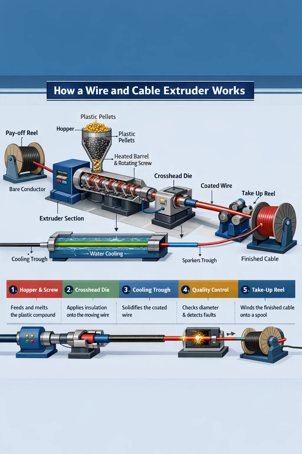
How a Wire and Cable Extruder Actually Works
A wire and cable extruder consists of several integrated subsystems. Each plays a distinct role in converting raw compound into a dimensionally stable, electrically sound insulated conductor.
The Barrel and Screw Assembly
The barrel is a hardened steel cylinder, typically bimetallic-lined for abrasion resistance when running filled compounds such as flame-retardant LSZH (Low Smoke Zero Halogen). Inside rotates the screw, whose geometry — flight depth, compression ratio, and L/D (length-to-diameter) ratio — is engineered for the specific compound family. PVC insulation commonly runs on screws with an L/D of 20:1 to 25:1 and a compression ratio near 3:1. Cross-linked polyethylene (XLPE) for medium-voltage power cable demands a longer, gentler screw, often 30:1 L/D, to avoid premature crosslinking in the barrel. Running the wrong screw in a wire and cable extruder causes degradation, uneven melt temperature, and ultimately rejects.
Barrel temperatures are zoned — typically four to six independent zones — rising from the feed throat to the metering section. For standard PVC, this might mean zone temperatures of 150 °C, 165 °C, 175 °C, and 180 °C toward the die. XLPE runs hotter at 200–220 °C in later zones. Precision PID controllers hold each zone within ±1 °C, because a 5 °C drift in melt temperature translates directly into viscosity variation and wall thickness scatter.
The Crosshead Die — The Heart of Wire Extrusion
What separates a wire and cable extruder from a standard profile extruder is the crosshead. The conductor enters the crosshead at a 90-degree angle (or in-line in some configurations) and exits coaxially through the die. Inside, the melt flow is redirected around the conductor using a torpedo or deflector, then converged by the die and tip geometry to deposit insulation evenly at all clock positions.
Two application methods exist within crosshead design:
- Pressure tooling — melt contacts the conductor inside the die, bonding under pressure. Used for most insulation applications where adhesion is required, such as XLPE power cable.
- Tubing tooling — the melt forms a tube that is drawn down onto the conductor after the die exit, relying on vacuum or draw-down ratio. Common for loose-fitting jackets on multi-core cables.
Die and tip sizing follows the draw-down ratio (DDR) and draw-down balance (DDB) formulas. A DDR between 1.2 and 1.5 is a typical starting point for medium-speed PVC lines. Exceeding DDR 2.5 on LSZH can introduce melt fracture — a rough, sharkskin surface on the insulation that fails spark testing.
Cooling Troughs and Downstream Equipment
After the die, the coated conductor enters a water-cooling trough. Trough length must match line speed and insulation wall thickness. A general rule is that a 1 mm wall PVC conductor running at 200 m/min requires at least 20–30 meters of active cooling. Insufficient cooling causes dimensional drift as the hot insulation deforms under capstan tension. Some XLPE medium-voltage lines run dry-cure tubes instead of water troughs for chemical crosslinking control, but water remains the standard for most wire and cable extrusion lines.
Inline instrumentation is non-negotiable on modern lines. A laser diameter gauge immediately after the die exit catches wall variation in real time, feeding closed-loop control back to the extruder screw speed or line speed. Spark testers at voltages from 1 kV to 15 kV, depending on insulation class, detect pinholes continuously. Capacitance monitors detect eccentricity — off-center conductors show as capacitance variation at the wire rotation frequency.
Types of Wire and Cable Extruders by Configuration
Not all wire and cable extruders are the same. The line configuration chosen has a direct impact on product range, changeover time, scrap rate, and capital investment.
| Extruder Type | Typical Screw Diameter | Primary Application | Max Line Speed |
|---|---|---|---|
| Single-screw (smooth bore) | 25–150 mm | PVC insulation & jacketing | Up to 800 m/min (fine gauge) |
| Single-screw (grooved feed) | 45–120 mm | HDPE, LSZH, PP compounds | Up to 600 m/min |
| Twin-screw (co-rotating) | 35–90 mm | Compounding LSZH, XLPE base | Compounding, not direct coating |
| Tandem dual extruder | Two screws, 45–90 mm each | Dual-layer insulation + jacket | Up to 500 m/min |
| Triple-layer (co-extrusion) | Three extruders feeding one die | MV/HV XLPE with semiconducting screens | 15–30 m/min (large cable) |
Single-Screw Extruder Lines
The single-screw wire and cable extruder dominates production volumes worldwide. Its simplicity — one screw, one barrel, one drive — means lower maintenance cost and faster screw change for product transitions. A 60 mm single-screw extruder running at 120 rpm can deliver 180–220 kg/h of PVC compound, which is sufficient to coat 1.5 mm² building wire at 400 m/min. For high-speed data cable production (Cat 6A, Cat 8), paired 30–45 mm extruders apply individual conductor insulation at line speeds exceeding 1,000 m/min.
Tandem and Co-Extrusion Lines
For cables requiring two or more discrete layers — such as an XLPE insulation with a bonded PVC jacket, or an automotive cable with a colored stripe layer over white base — tandem or co-extrusion lines feed separate compounds into a dual-channel crosshead. This eliminates a rewinding pass, saving 15–25% in processing cost on multi-layer products. Triple co-extrusion is mandatory for medium-voltage XLPE cable where the inner and outer semiconducting screens must bond to the insulation while still molten, with no contamination at the interfaces.
Key Materials Processed on Wire and Cable Extruders
Material selection drives the entire extruder specification — screw geometry, barrel metallurgy, temperature profile, and cooling capacity. Below are the primary compound families and their processing characteristics.
PVC (Polyvinyl Chloride)
PVC remains the most widely processed compound on wire and cable extruders globally, accounting for roughly 35–40% of all cable insulation volume by weight. It processes easily between 160–190 °C, accepts a wide range of plasticizer and flame-retardant additive packages, and is cost-effective. The challenge is thermal sensitivity — above 200 °C or with excessive shear, PVC degrades and releases HCl, which corrodes the barrel and crosshead. Screws for PVC use relatively low compression ratios (2.5–3.0:1) and polished, chrome-plated flights to reduce adhesion.
XLPE (Cross-Linked Polyethylene)
XLPE is the standard insulation for medium-voltage (1–35 kV) and high-voltage power cables. The crosslinking reaction — whether peroxide-initiated or silane moisture-cure — must happen after the die, not inside the extruder barrel. This constrains screw design to avoid excessive shear heating and requires a longer, low-compression screw. Dry-cure nitrogen tubes maintain temperatures above 200 °C for peroxide systems, then a cooling zone before the capstan. Silane-XLPE systems use a simpler single-screw extruder but require a post-extrusion sauna or hot water bath to complete the crosslink reaction.
LSZH / LSOH Compounds
Low Smoke Zero Halogen (LSZH) compounds are formulated with mineral fillers — aluminum trihydrate (ATH) or magnesium hydroxide — at loadings of 50–65% by weight. These fillers make LSZH highly abrasive and significantly raise melt viscosity compared to PVC. Wire and cable extruders running LSZH require bimetallic barrels (minimum 60 HRC wear surface), hardened alloy screws, and larger-diameter crossheads to manage the higher pressure drop. Output rates are 20–30% lower than equivalent PVC runs, and line speeds are typically capped at 200–400 m/min depending on gauge. LSZH is mandatory in tunnels, marine vessels, offshore platforms, and public buildings under IEC 60332 and EN 50266 fire standards.
Fluoropolymers (PTFE, FEP, ETFE)
Fluoropolymer-insulated cables are used in aerospace, military, and high-temperature industrial applications where continuous service at 150–260 °C is required. PTFE is technically a paste extrusion process (ram extrusion), not conventional screw extrusion. FEP and ETFE are melt-processable on specialized wire and cable extruders with all-PTFE-lined melt paths or nickel-alloy construction — fluoropolymers are corrosive to standard steel at processing temperatures of 340–380 °C. Output rates are low and tooling costs are high, but the performance premium justifies the investment for aviation wire bundles and electronic wiring harnesses.
TPE, TPU, and Rubber-Like Compounds
Thermoplastic elastomers (TPE) and thermoplastic polyurethane (TPU) have grown rapidly in automotive, robotics, and portable power tool cable applications, replacing vulcanized rubber in many cases. They are extrudable on standard wire and cable extruders with modest screw modification, process at 190–220 °C, and eliminate the vulcanization step entirely. TPU in particular offers outstanding abrasion resistance — 10 to 50 times that of PVC — making it the preferred jacket for drag-chain cables and industrial robot cables that flex millions of cycles.
Critical Parameters That Define Extrusion Quality
Quality in wire and cable extrusion is not a single variable. It is the result of controlling several interdependent parameters simultaneously, often through closed-loop automation on modern lines.
Eccentricity and Wall Thickness Uniformity
Eccentricity — the off-center position of the conductor within the insulation — directly affects the cable's dielectric strength and its ability to pass high-voltage withstand tests. IEC 60227 and UL 44 specify maximum eccentricity values; for a 1.5 mm² PVC building wire with 0.7 mm nominal wall, the minimum wall must not fall below 80% of nominal at any point. This means maximum eccentricity is ±0.14 mm on a 0.7 mm wall. Achieving this consistently at 500 m/min requires a concentricity-controlled crosshead with die-centering bolts, upstream conductor guide, and ideally an in-line capacitance monitor feeding back to the crosshead actuators.
Melt Temperature and Melt Pressure Stability
Melt pressure at the die head is a primary indicator of process stability. Pressure fluctuations — caused by screw vibration, inconsistent pellet feed, or worn screw flights — appear directly as diameter variation in the finished cable. A stable wire and cable extruder holds melt pressure variation below ±2 bar at steady state. Some lines use a gear pump between the extruder and crosshead specifically to decouple screw output variation from die pressure, enabling diameter control to ±0.003 mm — required for precision coaxial cable and fiber optic loose-tube jackets.
Line Speed and Capstan Control
The capstan (haul-off unit) sets the draw-down ratio and directly controls the final insulation diameter. A servo-driven capstan with dancer roll tension feedback responds to diameter gauge readings within 50–100 ms on modern CNC line controls. Tight speed regulation — better than ±0.1% velocity variation — is essential for thin-wall insulation where even a 0.5% speed excursion produces measurable diameter change. Line speed is also the primary throughput lever: doubling line speed from 200 to 400 m/min doubles output on the same extruder, so capstan stability directly impacts profitability.
Surface Quality and Spark Test Performance
Surface defects — pits, bubbles, streaks, or rough texture — can mask as electrical failures at spark testing. Bubbles in the insulation are caused by moisture in the compound (solved by pre-drying pellets to below 0.05% moisture), volatile additives, or dissolved air in the melt. Streaks often indicate degraded material or contamination in the crosshead. A clean wire and cable extrusion line runs continuous spark testing at 100% of production, with pass rates above 99.8% being the industry benchmark for volume insulation lines.
Wire and Cable Extruder Line Layout and Auxiliary Equipment
A complete wire and cable extrusion line is more than the extruder itself. The layout of auxiliary equipment determines startup scrap, changeover time, and final product dimensional consistency.
A typical insulating line from pay-off to take-up includes:
- Pay-off unit — holds the bare conductor reel, often with a tension-controlled dancer arm and reel change capability (active or static pay-off). Reel weights up to 3,000 kg for large-gauge power cables.
- Straightener and pre-heater — straightens coiled conductor and removes moisture or oxidation from the surface, improving insulation adhesion. Conductor pre-heat to 60–120 °C is standard for XLPE power cable.
- Wire and cable extruder with crosshead — the core unit, applying insulation or jacket.
- Cooling troughs — water cooling, typically in two or three serial sections with decreasing temperature (hot, warm, cold) to avoid thermal shock and residual stress in the insulation.
- Inline measurement — laser OD gauge, capacitance monitor, spark tester, and optionally a wall thickness X-ray scanner for precision cables.
- Capstan and dancer — haul-off unit maintaining line tension and speed.
- Marking unit — inkjet or engraving unit for meter marks, voltage rating, standard certifications, and color coding.
- Take-up / reeling — spool winder or drum twister, with automatic cut-and-transfer on accumulator-equipped lines to avoid line stops.
Total line length ranges from 20 meters for a small building wire insulating line to over 150 meters for a medium-voltage XLPE line with long cure tubes. Floor space planning and proper alignment of all units on a rigid steel base frame are fundamental — misalignment between pay-off and crosshead by as little as 2–3 mm at high speed causes conductor vibration and eccentricity spikes.
Extrusion Defects in Wire and Cable Production and How to Resolve Them
Even well-maintained wire and cable extruder lines encounter defects during production. Recognizing the cause quickly avoids extended scrap runs.
| Defect | Most Common Cause | Corrective Action |
|---|---|---|
| Diameter variation (cycling) | Screw surge, worn screw tip, or unstable melt pressure | Install gear pump; inspect and replace worn screw components |
| Bubbles / voids in insulation | Compound moisture above 0.05%; volatile plasticizers | Pre-dry compound 2–4 h at 70–80 °C; review additive package |
| Rough/sharkskin surface | Melt fracture — excessive die wall shear rate | Increase die temperature; reduce line speed; use processing aid |
| High eccentricity | Conductor vibration; misaligned die tip; guide tube wear | Re-center crosshead; replace guide tube; check conductor tension |
| Streaks / discoloration | Degraded material holdups in crosshead dead zones | Purge crosshead; disassemble and clean; check dead zones in die |
| Spark test failures (pinhole) | Contamination; bubbles; thin spot from eccentricity | Screen compound; address eccentricity; review material cleanliness |
Selecting a Wire and Cable Extruder for Your Production Requirements
Choosing the right wire and cable extruder starts with a clear definition of the product range, compound families, required throughput, and floor space constraints. Key specifications to define before requesting machine quotations include:
- Conductor size range — from minimum (e.g., 0.1 mm² for data cable) to maximum (e.g., 300 mm² for power cable). This determines crosshead bore size and screw diameter.
- Compound family and wall thickness — PVC/LSZH/XLPE each requires specific screw geometry. Minimum wall thickness drives die and tip selection.
- Target output in kg/h — calculated from line speed × linear weight of the insulated cable. This sizes the extruder screw diameter and drive motor.
- Required dimensional tolerances — standard building wire tolerances (IEC 60227) are achievable with basic gauge feedback, while automotive (ISO 6722) or aerospace standards require gear pump and X-ray wall measurement.
- Number of layers — single-layer insulation vs. dual-layer (insulation + jacket) vs. triple co-extrusion determines whether a single, tandem, or full co-extrusion line is needed.
- Automation level — fully automated reel change, splicing, and closed-loop diameter control add capital cost but reduce labor and startup scrap on high-speed lines by 30–60%.
A 60 mm wire and cable extruder with a 25:1 L/D screw, gear pump, and inline laser gauge is a common starting specification for a general-purpose PVC/LSZH building wire insulation line in the 0.75–16 mm² range. Expect installed line prices from $300,000 to $800,000 USD depending on automation level and market. For XLPE medium-voltage cable production, triple co-extrusion lines start from $2 million and can exceed $8 million for full dry-cure VCV vertical towers.
Extrusion in Specialized Cable Applications
Automotive Wire Harness Cables
Automotive wire harness cables are among the most demanding in terms of dimensional consistency and throughput. A typical automotive OEM wiring harness plant consumes millions of meters per day of insulated wire in gauges from 0.13 mm² to 6 mm². Wire and cable extruder lines for this sector operate at 600–1,200 m/min on fine gauge, with wall thicknesses as low as 0.15 mm on 0.13 mm² conductor. Compound choices include PVC (standard), XLPE, and increasingly ETFE or PP for high-temperature zones near the engine where 125°C or 150°C continuous ratings are required. Color-coded insulation is critical for harness assembly, so accurate color matching with inline colorimetric checks is standard on automotive lines.
Submarine and High-Voltage Cable
At the opposite extreme in terms of scale, submarine power cable and extra-high-voltage (EHV) land cable use the largest wire and cable extruder configurations available. Conductor cross-sections from 500 mm² to 2,500 mm² require triple co-extrusion lines where the inner semiconducting screen, XLPE insulation, and outer semiconducting screen are applied in a single pass at 3–10 m/min. Insulation wall thicknesses of 15–25 mm demand extremely high volumetric output from large screw extruders (120–200 mm diameter) and long nitrogen cure tubes of 50–80 meters. The insulation cleanliness requirements at 220–525 kV cable class are extraordinary — metallic particles larger than 125 microns in the XLPE are prohibited, requiring ultra-clean compound handling and cleanroom assembly areas around the crosshead.
Data and Telecommunications Cables
Structured cabling for Cat 6, Cat 6A, and Cat 8 Ethernet, as well as coaxial cables for broadband distribution, imposes tight capacitance and impedance uniformity requirements rather than voltage withstand demands. For solid-core Cat 6A, the insulation is typically foamed FEP or solid HDPE at 0.25–0.35 mm wall on 0.57 mm conductor, produced at 800–1,000 m/min. The foaming process — either physical foaming with nitrogen injection or chemical foaming with azodicarbonamide — reduces dielectric constant from 2.3 (solid HDPE) to 1.5–1.8 (foamed), which is what enables Cat 6A to reach 500 MHz bandwidth. Diameter control on a foamed insulation wire and cable extruder must be tighter than ±0.005 mm to maintain impedance within the ±3 Ω tolerance of TIA-568 standards.
Maintenance Practices That Extend Wire and Cable Extruder Service Life
A wire and cable extruder is a capital-intensive asset. Proper maintenance directly translates to uptime, consistent quality, and screw/barrel service life measured in years rather than months.
- Screw and barrel wear monitoring — measure barrel bore diameter and screw flight diameter every 6–12 months using calibrated instruments. When the diametric clearance between screw and barrel exceeds 0.4–0.6 mm (depending on screw size), output consistency drops and leakage flow increases. Replacing the screw before the barrel reaches the same wear stage is typically more cost-effective than replacing both simultaneously.
- Crosshead cleaning frequency — LSZH and pigmented compounds require crosshead disassembly and cleaning every 8–24 production hours to remove degraded material holdups. PVC natural compound on a clean line may run 200–500 hours between cleanings. A scheduled purge cycle using a heat-stable purging compound before shutdown removes residue without disassembly and extends the interval.
- Barrel heater and thermocouple inspection — faulty heater bands and thermocouples cause temperature zone anomalies that are often misdiagnosed as compound or screw problems. Replace thermocouples as a preventive measure every 12–18 months; inspect heater clamps for loosening and hot spots quarterly.
- Drive and gearbox service — extruder gearboxes operate under high, cyclic torque loads. Follow OEM-specified gear oil change intervals, typically every 4,000–8,000 hours. Vibration analysis on the gearbox twice per year identifies bearing wear before catastrophic failure and unscheduled downtime.
- Gauge and spark tester calibration — laser diameter gauges require calibration against NIST-traceable reference targets monthly. Spark testers must be verified against a known holiday (pinhole in insulation) at the beginning of each shift; an uncalibrated spark tester that misses failures is worse than no tester at all.
Industry Trends Shaping Wire and Cable Extrusion Today
Wire and cable extrusion technology is evolving alongside the broader cable industry's shift toward EV charging infrastructure, renewable energy interconnection, and high-speed data networks.
EV Charging Cable Demand
Electric vehicle DC fast charging cables require flexible TPU or silicone jackets capable of handling continuous current up to 500 A at 1,000 V DC, with bend radii below 30 mm at -40°C. These cables use liquid-cooled conductor designs with extruded insulation over a copper tube carrying cooling fluid. The wire and cable extruder lines for this product must handle multiple simultaneous layer applications — insulation over the copper conductor, sheath over the assembly — while maintaining the flexibility properties that allow the cable to hang and recoil thousands of times in service. Global EV charging cable demand is forecast to grow at over 20% CAGR through 2030, driving significant investment in new wire and cable extruder capacity.
Industry 4.0 and Digital Extrusion Lines
Modern wire and cable extruder control systems connect all line components — extruder drive, barrel temperatures, gear pump, diameter gauge, capstan, and take-up — through a single PLC or PC-based HMI with recipe management and SPC data logging. Digital extrusion lines store process recipes for hundreds of cable types, eliminating manual setup and enabling tool-free product changeover in under 15 minutes on well-designed systems. OPC-UA connectivity allows the line to feed real-time production data into MES and ERP systems, enabling traceability from compound lot to finished reel — a mandatory capability for automotive IATF 16949 certification and increasingly required for utility cable projects.
Sustainable and Recyclable Compound Extrusion
Regulatory pressure under the EU's Circular Economy Action Plan and REACH regulations is accelerating the shift from non-recyclable thermoset (XLPE) and halogenated (PVC) insulations toward thermoplastic XLPE alternatives (TR-XLPE, HFFR-TP) that can be recycled at end of life. These new compounds are processable on existing wire and cable extruder platforms with screw modification but require narrower process windows and more precise temperature control than legacy PVC. Compound suppliers and extruder OEMs are co-developing new tooling geometries and barrel coatings to handle these materials efficiently, with several commercial lines already running TR-XLPE compounds for medium-voltage cable at production scale in Europe and Asia.