 E-mail: info@gem-cablesolution.com
 Address: No.8 Yuefeng Rd, High Tech Zone, Dongtai, Jiangsu, China | No.109 Qilin East Rd, Daning, Humen, Dongguan, Guangdong, China.
 English
  English
 русский
 日本語
日本語 Español
 عربى
عربى 中文简体
中文简体
Content
- 1 What Is a Large Scale Wire Extrusion Machine?
- 2 Core Machine Categories and Output Ranges
- 3 Screw Design: The Engine of Throughput and Melt Quality
- 4 Crosshead Die Technology and Concentricity Control
- 5 Cooling Line Design: Why Length Determines Speed
- 6 Drive Systems, Torque, and Energy Efficiency
- 7 Barrel and Temperature Zone Management
- 8 Inline Quality Monitoring Systems
- 9 Materials Processed on Large Scale Wire Extrusion Machines
- 10 How to Evaluate and Select a Large Scale Wire Extrusion Machine
- 11 Automation and Industry 4.0 Integration
- 12 Maintenance Schedules and Wear Parts Planning
- 13 Leading Manufacturers and Global Supply Landscape
- 14 XLPE and High-Voltage Cable Extrusion: Specialized Requirements
- 15 Market Trends Driving Large Scale Wire Extrusion Machine Investment
- 16 Frequently Asked Questions
If you are sourcing or specifying a large scale wire extrusion machine, the short answer is this: output capacity, die-head precision, screw geometry, and cooling line length are the four variables that separate a machine that pays for itself in eighteen months from one that sits underutilized. A wire and cable extruder built for high-volume production must maintain tight wall-thickness tolerances—typically ±0.05 mm or better—across multi-shift runs while keeping scrap rates below 1%. Everything else—brand, color, cabinet finish—is secondary. The sections below break down every dimension of selection, operation, and optimization so your purchasing team has the technical depth to ask the right questions.
What Is a Large Scale Wire Extrusion Machine?
A large scale wire extrusion machine is a continuous-processing line that forces a molten thermoplastic or thermoset compound through a crosshead die, coating a moving conductor—copper, aluminum, or optical fiber—with an insulating or jacketing layer. Unlike small bench-top units used in laboratories, industrial-grade wire and cable extruder systems are engineered to run at line speeds from 100 m/min up to 2,500 m/min for thin enamel insulation, while maintaining consistent electrical-grade dielectric properties across kilometers of output.
The machine itself is a tightly integrated production line rather than a single piece of equipment. It consists of a pay-off stand, a preheat or annealing station, the extruder barrel-and-screw assembly, a crosshead die, a spark-test or capacitance monitor, a cooling trough, a caterpillar or capstan take-up, and a coiler or reeling station. Each subsystem must be matched to the others in throughput capacity, or the bottleneck becomes the ceiling for the entire line.
Core Machine Categories and Output Ranges
Not every wire and cable extruder operates at the same scale. Understanding the segmentation helps buyers match machine class to production volume before talking to suppliers.
| Machine Class | Screw Diameter (mm) | Typical Output (kg/hr) | Target Application | Approx. Line Speed (m/min) |
|---|---|---|---|---|
| Micro / Precision | 20–45 | 5–60 | Medical wire, magnet wire, data cables | 200–2,500 |
| Medium Industrial | 45–90 | 60–300 | Building wire, automotive harness, control cable | 50–400 |
| Large Scale / Heavy | 90–150+ | 300–1,200+ | Power cables, submarine cables, HV/EHV jacketing | 5–80 |
| Tandem / Triple-Layer | Multiple barrels | 400–2,000+ | XLPE insulated MV/HV cable, co-extrusion jacketing | 3–30 |
The dividing line between "medium industrial" and "large scale" is generally accepted in the industry at around 90 mm screw diameter for single-screw machines, because above that threshold the motor drive package, gearbox torque ratings, and barrel heating capacity all jump into a different engineering class. Many Chinese manufacturers, European OEMs such as Rosendahl Nextrom, and American builders like Davis-Standard define their large-scale wire and cable extruder portfolios starting at this diameter.
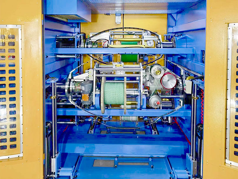
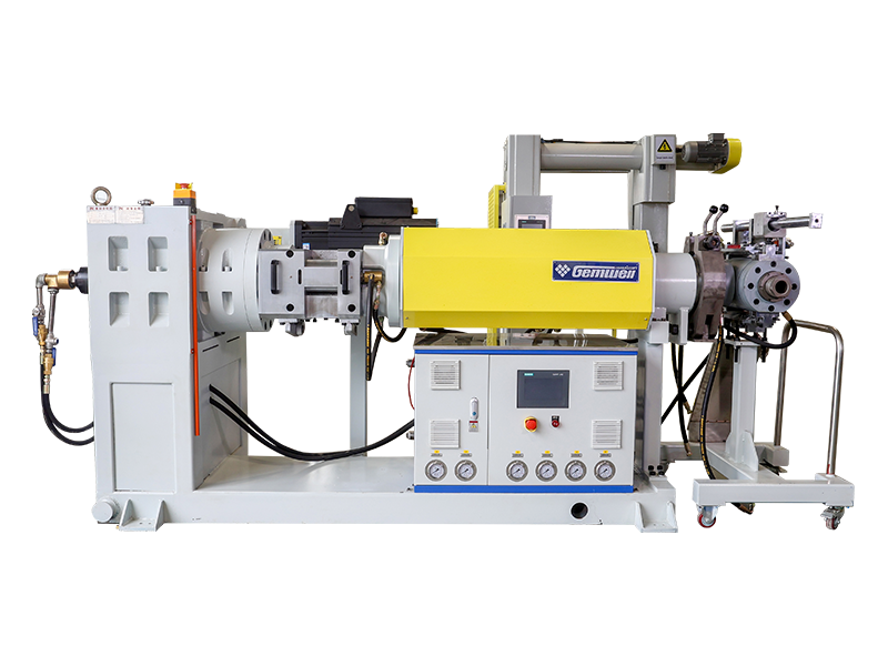
Screw Design: The Engine of Throughput and Melt Quality
The extrusion screw is the heart of any large scale wire extrusion machine. Its geometry—compression ratio, L/D ratio, and flight profile—determines melt temperature uniformity, output stability, and compound degradation risk. Getting these parameters wrong is the most common cause of insulation voids, surface defects, and eccentric coatings.
L/D Ratio
The length-to-diameter ratio (L/D) defines how much time the polymer spends in the barrel being plasticized and homogenized before reaching the die. For wire and cable compounds, the industry-standard range is 20:1 to 30:1. PVC insulation lines often run at 20:1 to 24:1 because PVC is thermally sensitive—longer residence time risks degradation. XLPE and HDPE lines may use 24:1 to 30:1 to ensure complete crosslink initiator dispersion. Some specialty halogen-free flame-retardant (HFFR) compounds now require L/D up to 35:1 due to their high filler loadings (ATH or MDH at 60–65% by weight), which demand more shear work to achieve uniform melt.
Compression Ratio
Compression ratio is the ratio of the feed-zone channel depth to the metering-zone channel depth. A wire and cable extruder processing unfilled polyethylene typically uses a compression ratio of 3.0:1 to 3.5:1. Filled compounds with ATH loadings above 55% require lower compression ratios—typically 2.2:1 to 2.8:1—to prevent screw overload and excessive shear heating that would prematurely activate crosslinking agents or degrade flame retardants.
Barrier and Mixing Sections
Modern high-output screws for large scale wire extrusion machines often incorporate barrier flights in the transition zone to separate the melt pool from unmelted solids, improving melt homogeneity without raising melt temperature. A downstream distributive mixing section—such as a Maddock or Egan mixer—further homogenizes colorants and stabilizer packages. The combination of a barrier screw with a Maddock mixer has been shown in published case studies by screw manufacturers like Xaloy and Reiloy to reduce melt temperature variation from ±8°C down to ±2°C, which directly translates into tighter capacitance and insulation resistance values on the finished cable.
Industry benchmark: A 120 mm screw with 28:1 L/D and barrier geometry processing XLPE compound at 150 rpm typically delivers 800–950 kg/hr output with melt temperature variation under ±3°C across the die head.
Crosshead Die Technology and Concentricity Control
The crosshead die is where the melted compound meets the moving conductor and is shaped into a precise cylindrical coating. On a large scale wire extrusion machine, die design directly controls eccentricity—the primary quality metric for insulated wire. Poor concentricity wastes material, causes dielectric failures, and triggers customer returns.
Pressure-Type vs. Tube-Type Die
A pressure-type (also called a "filling" die) builds melt pressure behind the tip so the compound adheres tightly to the conductor under positive pressure. It is used for building wire, hookup wire, and most PVC applications. A tube-type die creates a polymer tube that is drawn down onto the conductor under tension—preferred for PTFE, ETFE, and some XLPE applications where bond strength is deliberately minimized to allow stripping.
Die Body Material and Temperature Uniformity
Large-scale crosshead bodies are typically machined from tool steel (H13 or P20) with chrome or titanium nitride (TiN) coating on flow surfaces to resist abrasion from filled compounds. Uniform temperature across the die body is essential: a 5°C differential between the top and bottom of a 150 mm die body can produce 0.08 mm eccentricity on a 6 mm² building wire, which is outside most international standards. Leading manufacturers now embed multiple independent resistance heaters and thermocouples in the die body, with closed-loop PID control on each zone.
Automatic Centering Systems
High-production wire and cable extruder lines increasingly integrate automatic concentricity control. An ultrasonic or X-ray wall-thickness monitor positioned immediately after the die sends real-time thickness data to a servo-driven die adjustment system that moves the tip position with 0.001 mm resolution. Automatic centering systems from suppliers such as Sikora AG and Zumbach Electronic can reduce eccentricity from a manual-adjust baseline of 8–12% down to 2–4%, which at volumes of 50,000 km/year translates into measurable compound savings.
Multi-Layer Co-Extrusion Heads
For medium- and high-voltage cables requiring a semiconductor inner screen, XLPE insulation, and semiconductor outer screen in a single pass, a triple co-extrusion crosshead is used. These heads have three separate melt flow channels that converge in a single die body, depositing all three layers simultaneously. This approach—sometimes called "dry cure" or "CCV" (catenary continuous vulcanization) when combined with an elevated-temperature curing tube—eliminates inter-layer contamination risk and maintains the cleanliness levels required by IEC 60840 for cables rated above 30 kV.
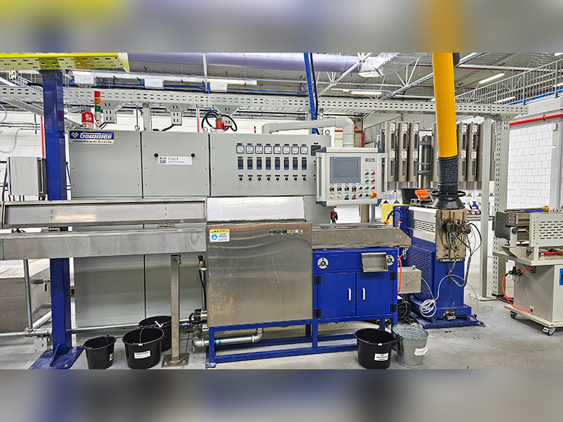
Cooling Line Design: Why Length Determines Speed
After the die, the hot insulated wire must be cooled from the melt temperature (typically 180–230°C for PE compounds, 170–200°C for PVC) down to below 60°C before it contacts the capstan or caterpillar, to prevent deformation under haul-off tension. The cooling trough length is therefore the primary determinant of maximum achievable line speed on any large scale wire extrusion machine.
Water Trough Sizing Rule
A simplified engineering rule used in the wire industry: cooling trough length (in meters) divided by line speed (m/min) must be sufficient to reduce the insulation surface temperature below 60°C. For a 2.5 mm² PVC building wire at 200 m/min, a 30-meter trough with 18–22°C inlet water is typically required. For a 50 mm² XLPE power cable at 40 m/min, a 60-meter trough with staged water temperature zones is common. Modern lines for large-scale production install troughs in sections of 6–10 meters each, allowing staged cooling and the ability to vary the number of active sections by product.
Spray vs. Immersion Cooling
Immersion tanks are standard for cables above 4 mm². High-speed precision wire lines for thin insulation (AWG 28 and finer) often use a first zone of air-cooled spark tester followed by a water spray box, because full immersion at speeds above 1,000 m/min creates turbulence that can cause the wire to oscillate and touch trough walls. Spray boxes with laminar-flow nozzles control this problem while still achieving adequate heat removal.
Chilled Water Systems
Large scale wire and cable extruder lines for automotive harness wire running at 600–800 m/min typically connect to a central chilled water system delivering 8–12°C water. The water inlet temperature directly affects the minimum trough length. Going from 22°C tap water to 10°C chilled water can reduce the required trough length by 25–35% for the same product and speed, a significant saving in floor space for high-volume plants.
Water Recirculation and Quality
Cooling water on a wire extrusion line accumulates compound residue, release agents, and microbial growth. Modern large-scale lines incorporate closed-loop recirculation with a central chiller, filtration to 50 microns, and UV sterilization. Water conductivity must be controlled below 50 µS/cm for high-voltage cable lines to prevent galvanic corrosion on copper conductors passing through the trough. Plants that neglect water quality management often find conductor surface oxidation creating adhesion problems at the insulation-conductor interface.
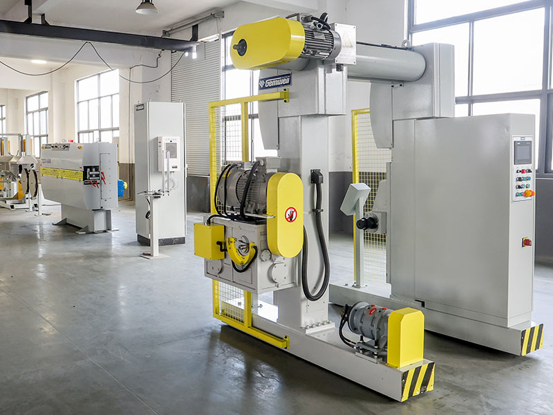
Drive Systems, Torque, and Energy Efficiency
The drive system on a large scale wire extrusion machine—the motor, gearbox, and variable frequency drive (VFD)—must deliver stable torque across the entire speed range to prevent surge and hunt, which manifest as diameter variation in the finished wire. In the past decade, AC vector drives and permanent magnet (PM) direct-drive systems have substantially displaced older DC thyristor drives on new installations.
AC Vector Drive + Helical Gearbox
The most widely used configuration on medium to large wire and cable extruder lines. The AC motor (typically IE3 or IE4 efficiency class) is coupled to a hardened helical or helical-bevel gearbox. Speed regulation accuracy is typically ±0.05% with a good vector drive, sufficient for most building wire and power cable applications. Motor sizes range from 75 kW for a 90 mm extruder to 630 kW or more for a 150 mm machine processing filled compounds.
PM Direct Drive
Permanent magnet motors with a single-stage reduction or no gearbox at all are increasingly common on high-speed precision wire extruders. Without a gearbox, mechanical losses drop to near zero, and the system achieves speed regulation better than ±0.01%. PM drives also reduce noise levels from the typical 82–86 dB(A) of a geared machine to below 75 dB(A), a meaningful improvement in operator environments running 24/7.
Specific Energy Consumption
A key purchasing metric is specific energy consumption (SEC) in kWh per kilogram of output. A well-configured 120 mm wire and cable extruder processing XLPE at high throughput should achieve 0.12–0.20 kWh/kg for the extrusion section alone. Older machines with DC drives and poor barrel insulation can run 0.35–0.50 kWh/kg. At an annual output of 5,000 tonnes, the difference between 0.15 and 0.40 kWh/kg amounts to 1,250 MWh/year—at industrial electricity rates of $0.08–$0.12/kWh, this is $100,000–$150,000 in annual energy cost difference.
Barrel Insulation and Zone Heating
Heating the barrel accounts for 20–40% of total extruder energy consumption during production. Ceramic band heaters with 94–96% efficiency, combined with mineral wool insulation sleeves fitted over the bands, reduce radiated heat loss and lower zone heating energy by 15–30% compared to uninsulated cast-aluminum band heaters. Several large-scale machine builders now offer insulated barrel heating as standard on machines above 90 mm.
Barrel and Temperature Zone Management
Precise barrel temperature control is non-negotiable in a production-grade wire and cable extruder. Most large-scale machines divide the barrel into four to six independent heating-and-cooling zones, each with its own resistance band heater, cooling blower (or water-jacket), and PID temperature controller. The ability to independently set and hold each zone within ±1°C of setpoint is the baseline requirement.
- Zone 1 (Feed): Typically set 20–40°C below the melt temperature to prevent bridging and ensure solid-bed conveying
- Zone 2–3 (Transition): Gradual ramp toward melt temperature, allowing controlled plasticization without overheating the melt
- Zone 4–5 (Metering): Set at or slightly below die temperature for stable melt pressure and output rate
- Adapter and Die Zones: Often independently controlled; die zone uniformity across the body within ±2°C is critical for concentricity
- Cooling medium: Compressed air or water jacket cooling to prevent overheating at high screw speeds
Temperature overshoot during startup is a frequent source of compound degradation and die contamination. Modern large scale wire extrusion machine controllers use auto-tune PID algorithms and model predictive control (MPC) for faster barrel warm-up with minimal overshoot—bringing a 120 mm machine to production temperature in 45–60 minutes with less than 3°C overshoot versus the 20–30°C overshoot common on older thyristor-controlled machines.
Inline Quality Monitoring Systems
Modern high-volume wire and cable extruder lines integrate multiple inline measurement and monitoring systems that generate data used for both immediate process control and long-term statistical quality management. This is one of the most rapidly evolving areas of the wire extrusion industry, driven by Industry 4.0 connectivity requirements from Tier 1 automotive OEMs and grid operators.
Laser micrometers scanning at 2,000+ Hz measure outer diameter and detect oval cross-section. Units from Zumbach, Sikora, and Beta LaserMike maintain ±0.001 mm resolution. Data feeds the haul-off speed control loop for real-time diameter correction.
Ultrasonic gauges (for opaque cables) or X-ray systems (for all cable types) provide 360° wall thickness measurement. Sikora's CENTERVIEW 8000 series provides real-time eccentricity data with ±0.01 mm measurement uncertainty for cables up to 60 mm OD.
Continuous capacitance monitors detect insulation voids and inclusions that cannot be seen by laser gauges. High-voltage spark testers apply 0.5–25 kV (depending on insulation thickness) to detect pinholes. Modern systems achieve 100% detection of pinholes above 50 µm in diameter at speeds up to 1,000 m/min.
Melt pressure transducers at the adapter and die inlet measure process stability. Output rate is directly proportional to die pressure at constant temperature; a pressure drift of more than 5% over 30 minutes signals a process problem requiring investigation. Melt thermocouples provide the actual melt temperature rather than barrel surface temperature.
Materials Processed on Large Scale Wire Extrusion Machines
A large scale wire extrusion machine must be configured specifically for the compound family it will run. Different polymers have radically different rheological behavior, thermal stability, and abrasion characteristics that affect screw design, barrel metallurgy, die material, and cooling requirements.
| Compound | Processing Temp (°C) | Key Screw Feature | Barrel Metallurgy | Main Application |
|---|---|---|---|---|
| PVC (flexible) | 160–185 | Low shear, low compression (2.5:1) | Chrome-plated or nitrided | Building wire, automotive wire |
| XLPE (crosslinkable PE) | 120–135 (die exit) | Barrier screw, low shear | Bi-metallic (Xaloy 306 type) | MV/HV power cable insulation |
| HDPE | 180–230 | High compression (3.5:1), barrier | Standard nitrided | Telecom cable, low-voltage jacketing |
| HFFR (ATH/MDH filled) | 190–220 | Low compression (2.2:1), high L/D | Bi-metallic, hardened flights | Railway, marine, tunnel cable |
| TPE / TPU | 170–210 | General-purpose, mixing section | Standard nitrided | Automotive, robotics flex cable |
| Fluoropolymers (FEP, ETFE) | 300–380 | Short L/D (16:1), corrosion-resistant | Inconel or Hastelloy lined | Aerospace, instrumentation wire |
How to Evaluate and Select a Large Scale Wire Extrusion Machine
Selecting a production wire and cable extruder requires more than comparing quoted output rates. The following structured evaluation process helps procurement engineers avoid the most common buying mistakes.
Define the Product Matrix First
List every wire gauge, insulation material, and line speed you will need in the first three years. The widest product range—not the most common product—defines the machine specification. A line optimized for 2.5 mm² PVC building wire at 300 m/min may not be able to run 95 mm² XLPE power cable at all, and a line built for HV cable cannot run thin hook-up wire economically. Many buyers under-specify by quoting only their highest-volume product.
Request Documented Screw Performance Data
Ask suppliers for screw characteristic curves: output (kg/hr) vs. screw speed (RPM) at your specific compound and processing temperature. Reputable wire and cable extruder manufacturers will have this data from factory acceptance testing or published trial records. A claimed output rate without screw speed and temperature context is meaningless.
Inspect Gearbox Torque Ratings
The gearbox is often the limiting component on large-scale machines. Request the rated torque in Nm and the safety factor relative to the motor's peak torque output. A gearbox rated for 1.0× motor peak torque with no safety margin will fail prematurely when processing high-viscosity filled compounds. Industry practice is a safety factor of 1.5× or higher on gearbox torque rating relative to motor peak.
Audit the Control System Architecture
Determine whether the line's PLC and HMI system is built on an open architecture (Siemens S7, Allen-Bradley ControlLogix, Beckhoff TwinCAT) or a proprietary platform. Proprietary control systems create long-term dependence on the original equipment manufacturer for software updates, spare parts, and modifications. Open architecture allows your engineering team to modify recipes and add sensors independently.
Conduct a Factory Acceptance Test (FAT)
Insist on a factory acceptance test with your compound and your conductor. Run the machine for at least four hours at rated speed and measure diameter variation (CV%), eccentricity, and melt pressure stability. Request that all FAT data be included in the delivery documentation. Suppliers who resist FAT terms on large-scale wire extrusion machine orders are a significant risk signal.
Automation and Industry 4.0 Integration
The wire and cable industry is under sustained pressure to reduce operator dependency and increase data traceability. Modern large scale wire extrusion machines are increasingly delivered as fully automated lines capable of recipe management, remote diagnostics, and production reporting without manual intervention between changeovers.
Recipe Management and Changeover Time
A well-configured large-scale wire and cable extruder with digital recipe management can execute a product changeover—switching from one wire gauge and compound to another—in under 20 minutes when all parameters (screw speed, barrel temperatures, haul-off speed, take-up tension) are stored and loaded as a single recipe file. Without recipe management, changeovers requiring manual adjustment of 30–50 parameters can take 90–120 minutes, representing 12–20% capacity loss on a busy three-shift line running 15 product changeovers per week.
OPC-UA Connectivity and MES Integration
The OPC Unified Architecture (OPC-UA) protocol is the current standard for connecting extrusion line data to plant-level Manufacturing Execution Systems (MES), ERP systems, and cloud analytics platforms. A large scale wire extrusion machine equipped with OPC-UA can stream screw speed, throughput, melt temperature, diameter, and spark test results in real time to a central database, enabling shift-by-shift process analytics and predictive maintenance triggers. Automotive cable suppliers serving Tier 1 customers in Europe are increasingly required by customer quality requirements to have 100% OPC-UA traceability to the meter of output.
Predictive Maintenance on High-Wear Components
Screw and barrel wear is the primary maintenance cost on a large scale wire extrusion machine. Vibration sensors on the gearbox, motor current trending, and melt pressure drift algorithms can provide 200–400 hours of advance warning before screw wear reaches the point of output instability. Several wire extruder OEMs now offer remote monitoring subscriptions where their engineering team reviews machine data weekly and flags anomalies before they become production stoppages.
Documented case: A medium-sized wire manufacturer in Southeast Asia reported a 34% reduction in unplanned downtime after implementing OPC-UA connectivity and a remote monitoring subscription on a fleet of three large-scale extruder lines. Payback period was estimated at under 8 months based on avoided downtime costs alone.
Maintenance Schedules and Wear Parts Planning
A large scale wire extrusion machine running three shifts, six or seven days per week will accumulate 7,000–8,000 operating hours per year. Structured preventive maintenance is the single most important factor in sustaining the output rate and product quality that justified the capital investment.
Daily and Weekly Tasks
- Check and log barrel zone temperatures and compare to setpoints
- Record melt pressure at the adapter and die; trend for drift
- Inspect cooling trough water clarity and conductivity
- Clean spark test electrode and check electrode gap
- Lubricate caterpillar/capstan bearings per OEM schedule
- Check gearbox oil level and temperature
Monthly Tasks
- Pull screw for visual inspection if processing abrasive filled compounds
- Calibrate temperature controllers against a certified reference thermocouple
- Test all safety interlocks (emergency stop, overload protection)
- Flush and replace cooling water filters
Annual Tasks and Wear Part Life
- Measure screw flight clearance against barrel bore; replace when clearance exceeds 0.2–0.3% of barrel diameter
- Full gearbox oil drain and refill with OEM-specified grade
- Replace barrel heater bands (typical life: 18,000–25,000 hours)
- Replace all thermocouple sensors (drift becomes significant after 2–3 years)
- Inspect thrust bearing condition (failure is typically the most expensive repair on a large-scale machine)
Screw and barrel life on a large scale wire extrusion machine running unfilled PE compounds can exceed 30,000–40,000 hours. The same machine running 60% ATH-filled HFFR compounds may require screw replacement after 4,000–6,000 hours if bi-metallic barrel and hardened-flight screws are not specified. The cost difference between a standard screw (~$8,000 for 120 mm) and a fully bi-metallic wear-resistant screw (~$22,000) is typically recovered in less than one year through reduced replacement frequency when running abrasive filled compounds.
Leading Manufacturers and Global Supply Landscape
The global market for large scale wire extrusion machines is supplied by a mix of European, North American, and Asian manufacturers. Understanding the supplier landscape helps procurement teams benchmark price, technology level, and after-sales capability.
Price benchmarks for large scale wire and cable extruder machines (screw diameter 90–120 mm, full line including cooling, take-up, and controls): Chinese-built lines start at approximately $180,000–$450,000 USD for a complete building wire line. Equivalent European-built lines are typically $600,000–$1,500,000 USD. For CCV or triple co-extrusion lines for HV cable, European packages start at $3,000,000 USD and can reach $25,000,000 for complete turnkey HV submarine cable extrusion systems.
XLPE and High-Voltage Cable Extrusion: Specialized Requirements
Medium- and high-voltage XLPE insulated cable extrusion represents the most technically demanding segment of the large scale wire extrusion machine market. The requirements differ from building wire extrusion so substantially that a plant intending to produce cables rated above 12 kV must treat it as an entirely separate technology category.
Cleanliness Requirements
XLPE compound for cables rated 30 kV and above must be processed in a cleanroom environment. According to IEC 60840, insulation for cables above 30 kV must have no contamination particles larger than 0.125 mm in the cross-section. This requires the entire extrusion line—from the compound silo to the die—to be enclosed in a Class 10,000 (ISO 7) cleanroom, with filtered air supply, positive pressure maintained at all times, and all personnel wearing lint-free garments. Compound handling uses closed-transfer systems to prevent contamination from ambient dust. These requirements substantially increase the civil engineering and mechanical requirements for the line installation compared to building wire production.
Continuous Vulcanization (CV) Systems
XLPE requires crosslinking after extrusion, accomplished by exposing the insulated cable to high temperature and pressure in a nitrogen-pressurized curing tube (CCV: catenary continuous vulcanization, or VCV: vertical continuous vulcanization). CCV tubes for HV cable are typically 80–200 meters long, maintained at 300–400°C and 10–20 bar nitrogen pressure. The catenary sag of the cable through this tube must be precisely controlled to prevent oval deformation of the soft uncured insulation. A VCV line uses a vertical tube (up to 300 meters tall, requiring a dedicated tower building) that eliminates catenary sag entirely, making it the preferred technology for cables 132 kV and above. VCV lines for EHV cable can cost EUR 15–30 million for the complete installation.
Degassing After Crosslinking
Crosslinked XLPE insulation contains byproducts of the peroxide decomposition process (methane, acetophenone, and cumyl alcohol for DCP-crosslinked systems). These byproducts must be diffused out of the insulation in heated degassing chambers (typically 70–80°C for 5–30 days depending on cable diameter) before cable accessories (joints, terminations) can be applied. Failure to adequately degas XLPE insulation results in space charge accumulation that can cause premature dielectric failure. Degassing is often the production rate bottleneck for HV cable manufacturers—building enough chamber capacity to match extrusion output requires significant capital investment in temperature-controlled warehousing.
Market Trends Driving Large Scale Wire Extrusion Machine Investment
Understanding the macro drivers of demand helps plant planners size and time new line investments correctly.
Grid Modernization and Renewable Energy
The global energy transition is driving unprecedented demand for high-voltage and extra-high-voltage cable. The International Energy Agency (IEA) estimated in its 2023 Electricity Grids and Secure Energy Transitions report that achieving net-zero emissions by 2050 requires 80 million km of new grid cable by 2040—approximately twice the length of all cable installed to date. This is creating investment in new HV and EHV cable lines at producers across Europe, North America, and Asia.
Electric Vehicle Expansion
EV production is driving demand for high-temperature, thin-walled automotive wire capable of handling higher current densities in lighter harnesses. Wire compounds such as cross-linked ETFE and silicone-insulated wire rated to 175°C and above are growing at double-digit rates. Automotive wire extruder lines optimized for these specialty compounds are a priority investment for harness manufacturers in Mexico, Morocco, and Eastern Europe supplying European and American OEMs.
Fiber Optic Infrastructure
Global fiber-to-the-premises (FTTP) buildout programs in the US (BEAD program: $42.45 billion), EU (Gigabit Infrastructure Act target: 1 Gbps to all EU households by 2030), and developing markets are driving cable sheath and buffer tube extrusion capacity additions. These lines use a wire and cable extruder adapted for fiber optic buffer and jacket applications, typically running HDPE or LSZH compounds at 200–600 m/min.
Reshoring and Supply Chain Localization
Post-2020 supply chain disruptions and geopolitical concerns have prompted wire and cable manufacturers in North America and Europe to invest in domestic production capacity that had previously been offshored. This trend is creating a wave of new large scale wire extrusion machine installations in markets that had not seen greenfield wire plant investment in two decades.


