E-mail: info@gem-cablesolution.com
 Address: No.8 Yuefeng Rd, High Tech Zone, Dongtai, Jiangsu, China | No.109 Qilin East Rd, Daning, Humen, Dongguan, Guangdong, China.
 English
  English
 русский
 日本語
日本語 Español
 عربى
عربى 中文简体
中文简体



Content
- 1 What Does a SATA Cable Do? The Direct Answer
- 2 How SATA Cables Transfer Data: The Technical Mechanism
- 3 SATA Power Cable: What It Does and Why It Matters
- 4 How Wire and Cable Extruder Technology Shapes SATA Cable Quality
- 5 Flat vs. Round SATA Cables: Construction Differences and When They Matter
- 6 Common Signs That a SATA Cable Is Failing
- 7 SATA Cables in Different Device Applications
- 8 SATA vs. Other Storage Interfaces: Where the Cable Fits in the Bigger Picture
- 9 Choosing the Right SATA Cable: What to Look for
- 10 How to Properly Connect and Route SATA Cables
- 11 The Manufacturing Chain Behind Every SATA Cable
What Does a SATA Cable Do? The Direct Answer
A SATA (Serial ATA) cable serves one core purpose: it creates a high-speed communication channel between a storage device — such as a hard disk drive (HDD), solid-state drive (SSD), or optical drive — and the motherboard of a computer. Without this cable, your system cannot read from or write to those storage devices, which means no operating system, no files, and no functioning computer in any practical sense.
There are actually two types of SATA cables working together in any storage setup: the SATA data cable, which transmits data signals between the drive and the motherboard, and the SATA power cable, which delivers electrical power from the power supply unit (PSU) to the drive itself. Both are essential — a drive with only one of the two connected simply will not function.
The physical construction of these cables — from the insulation thickness to the conductor purity — depends significantly on the manufacturing process behind them. Modern SATA cables are produced using precision wire and cable extruder machinery that applies insulation uniformly over copper conductors, ensuring signal integrity across the entire length of the cable. This manufacturing detail is not trivial; it directly affects transfer speeds, heat resistance, and long-term durability.
How SATA Cables Transfer Data: The Technical Mechanism
SATA uses a serial transmission method, meaning data bits are sent one at a time in a continuous stream rather than in parallel. This was a significant departure from the older PATA (Parallel ATA) standard, which sent multiple bits simultaneously but required wide ribbon cables and suffered from crosstalk interference at higher speeds.
The SATA data cable contains 7 pins and 3 conductors: two pairs of differential signal lines for transmitting and receiving data, and three ground lines that reduce electromagnetic interference. Differential signaling means the cable sends the same signal twice — once normally and once inverted — and the receiving device compares the two to filter out noise. This approach allows SATA cables to operate reliably at high frequencies without the interference problems that plagued older standards.
SATA Generation Speed Comparison
| SATA Generation | Interface Speed | Real-World Throughput | Common Use |
|---|---|---|---|
| SATA I (1.0) | 1.5 Gb/s | ~150 MB/s | Legacy HDDs |
| SATA II (2.0) | 3 Gb/s | ~300 MB/s | Mid-range HDDs, early SSDs |
| SATA III (3.0) | 6 Gb/s | ~600 MB/s | Modern SSDs and HDDs |
SATA III, which operates at 6 Gb/s with an effective throughput ceiling of around 600 MB/s, is the current standard used in virtually all consumer desktop and laptop builds. The physical cable itself is backward-compatible across all three generations — a SATA III cable can connect a SATA I drive — though speeds will be limited to the slower device's maximum.
SATA Power Cable: What It Does and Why It Matters
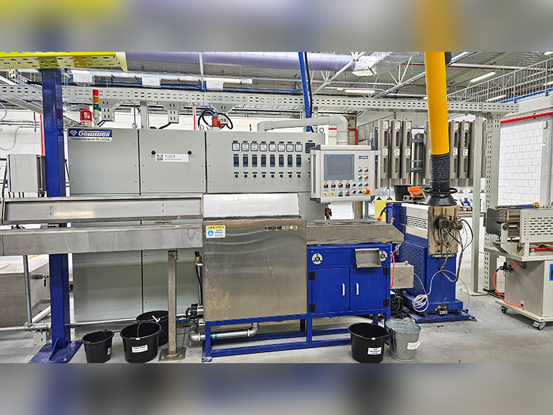
The SATA power connector is a 15-pin plug that delivers three separate voltage levels to the connected drive: 3.3V, 5V, and 12V. Each voltage serves a different function within the drive's internal components. The 12V line primarily powers the motor in hard disk drives, spinning the platters at 5,400 or 7,200 RPM. The 5V line powers the drive's logic board and read/write electronics. The 3.3V line, introduced in the SATA standard revision, is used by some modern SSDs for their low-power controller circuits.
The 15-pin SATA power connector replaced the older 4-pin Molex connector used in PATA systems. It offers a far slimmer profile, easier routing inside a case, and the ability to carry all three voltage levels simultaneously through a single connector. A typical 2.5-inch laptop-style SSD only draws from the 5V line, consuming as little as 1–3 watts under load, while a 3.5-inch desktop hard drive spinning at 7,200 RPM may draw up to 8–10 watts during seek operations — primarily through the 12V rail.
The quality of the wiring within the SATA power cable — particularly the gauge of the copper conductors and the consistency of insulation — affects voltage stability under load. This is where manufacturing processes such as those used in wire and cable extruder production become directly relevant to real-world performance.
How Wire and Cable Extruder Technology Shapes SATA Cable Quality
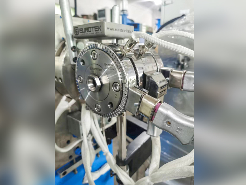
Every SATA cable begins its life on an extrusion line. A wire and cable extruder is a machine that forces molten thermoplastic material — most commonly PVC (polyvinyl chloride), LLDPE (linear low-density polyethylene), or FEP (fluorinated ethylene propylene) — through a die around a copper conductor, creating a consistently coated wire. This is not a secondary detail; the quality of extrusion determines insulation thickness uniformity, dielectric properties, temperature resistance, and how well the cable holds up over years of use.
In the production of SATA cables specifically, the wire and cable extruder must apply insulation to very fine conductors with extreme precision. SATA data cables typically use 28 AWG conductors for signal lines and 26 AWG conductors for ground lines. At these gauges, even a small deviation in insulation thickness — say, 0.02mm off from spec — can change the cable's impedance characteristics and affect signal integrity at the 6 Gb/s frequencies SATA III demands.
What Extrusion Quality Affects in the Finished Cable
- Impedance control: SATA cables are specified to maintain a differential impedance of 100 ohms (±10%). Extrusion inconsistencies cause impedance variations that produce signal reflections and data errors.
- Dielectric constant: The insulating material chosen and how uniformly it is applied by the wire and cable extruder determines how fast signals propagate through the cable — directly impacting latency at the nanosecond level.
- Temperature resistance: PVC insulation extruded to proper thickness can typically handle temperatures from -20°C to 80°C. Thin spots created by poorly calibrated extruder machinery lead to insulation breakdown under sustained heat from a loaded drive or a warm case interior.
- Flex life: How many times a cable can be bent without cracking depends on insulation cross-link density and extrusion consistency. Budget cables often fail at the connector entry points after repeated flexing.
- Conductor adhesion: Proper extrusion temperature and pressure ensures the insulation bonds cleanly to the conductor jacket without voids, which would allow moisture ingress over time.
High-end cable manufacturers run their wire and cable extruder lines with real-time spark testing and diameter gauging systems that check every meter of extruded wire for defects. Consumer-grade SATA cables from reputable brands typically pass through these quality controls. Ultra-cheap cables from unknown suppliers — often sold in bulk online — frequently skip these steps, resulting in cables that work fine initially but develop intermittent errors within 12–18 months.
Flat vs. Round SATA Cables: Construction Differences and When They Matter
SATA data cables come in two main physical formats: flat (ribbon-style) and round. Both carry the same 7-pin signal arrangement, but their internal construction and practical behavior differ considerably.
Flat SATA cables are the default style shipped with most motherboards. The conductors are laid side-by-side and encased in a flat thermoplastic sheath, typically produced by a flat cable wire and cable extruder or a laminating process. They are inexpensive to produce, lie neatly against surfaces, and are easy to route along the inside edges of a PC case. However, they have limited bend radius — forcing them into tight curves can kink the conductors and cause signal degradation or physical damage to the insulation at stress points.
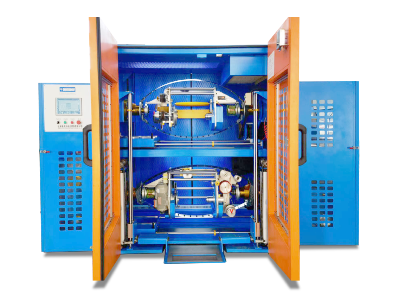
Round or braided SATA cables have individually insulated conductors twisted or bundled together inside a round outer jacket. This construction provides better flexibility, makes routing through tight cable management channels easier, and offers marginally better EMI shielding due to the twisted-pair arrangement of the signal conductors. They cost more to manufacture because each conductor must pass through a wire and cable extruder separately before assembly.
Right-Angle vs. Straight Connectors
Beyond flat vs. round, SATA cables also come with straight or right-angle (90-degree) connectors on one or both ends. The right-angle connector is specifically useful when a drive is mounted close to the side panel of a case, where a straight connector would protrude outward and potentially block airflow or prevent the panel from closing. Right-angle connectors introduce a small mechanical stress concentration at the bend point, so cable quality — particularly the robustness of the overmold at the connector entry — becomes more important in these configurations.
Common Signs That a SATA Cable Is Failing
SATA cables do fail, and they do so more often than most people expect. Because the symptoms of a failing cable closely mimic the symptoms of a failing drive, cables are frequently overlooked during troubleshooting. Knowing what to look for saves time and prevents unnecessary drive replacements.
- Intermittent drive detection: The BIOS or operating system sees the drive sometimes but not others. This is a classic symptom of a loose or damaged SATA data cable connector that is not making consistent contact with the pins.
- Frequent read/write errors: Applications report errors when accessing files, or the OS logs disk errors in the event viewer. If SMART diagnostics show the drive itself is healthy, the cable is the next logical suspect.
- Sudden performance drops: A SATA III SSD that normally reads at 500 MB/s suddenly tests at 150 MB/s. This speed matches SATA I bandwidth — a sign that the link is negotiating down to the lowest common denominator due to signal errors on a degraded cable.
- Clicking or not-spinning drives: While these usually indicate a mechanical drive problem, power cable issues can cause a drive to not receive adequate voltage to spin its motor, producing similar symptoms.
- Boot failures after case moves: Moving a PC causes cables to flex and shift. A cable that was borderline functional can lose contact entirely after a single relocation.
The fix in all these cases is often a $3–$8 replacement cable, yet people frequently spend hours running diagnostics on a perfectly good drive. Always swap the cable first when storage problems appear suddenly without prior symptoms of drive wear.
SATA Cables in Different Device Applications
While desktop PCs are the most common context for SATA cables, the interface appears across a wide range of hardware — and the cable requirements shift depending on the application.
Desktop Computers
Standard 3.5-inch hard drives and 2.5-inch SSDs in desktop towers use full-size SATA data and power connectors. Motherboards in the ATX form factor typically provide 4 to 8 SATA ports, allowing multiple drives. High-end HEDT (High-End Desktop) boards can offer up to 12 SATA ports for storage-intensive builds like NAS servers or video editing workstations.
Laptop Computers
Laptops use 2.5-inch drives with the same SATA interface, but the cable is usually a very short, sometimes direct-connect ribbon integrated into the drive bay assembly. Aftermarket SATA cables for laptops must be made to exact length and flexibility specifications — here, the flex properties of the cable jacket, determined partly by wire and cable extruder material choices, become critical because the cable endures stress every time the chassis flexes during normal use.
Servers and NAS Devices
In server environments, SATA cables must meet higher durability standards because drives are accessed continuously, often 24/7. Server-grade cables use heavier insulation materials and locking connectors to prevent accidental disconnection. Some enterprise setups use eSATA (External SATA) for connecting external storage enclosures — a variant that uses a different physical connector but the same signaling protocol, with cables that are shielded against external EMI and rated for longer runs up to 2 meters versus the typical 1-meter limit of internal SATA cables.
Optical Drives and Specialized Hardware
DVD and Blu-ray drives also use standard SATA connections, as do some tape drives and certain industrial embedded systems. The cable performs the same function in all of these: establishing a data path and delivering power. Industrial applications sometimes require cables with wider temperature ratings, which means manufacturers must use different insulation compounds through their wire and cable extruder lines — materials like cross-linked polyethylene (XLPE) instead of standard PVC, rated for continuous operation at 90°C or higher.
SATA vs. Other Storage Interfaces: Where the Cable Fits in the Bigger Picture
Understanding what a SATA cable does also means understanding where it sits relative to other storage connection technologies, particularly as NVMe and M.2 drives have become mainstream.
| Interface | Max Speed | Cable Required | Primary Use |
|---|---|---|---|
| SATA III | 600 MB/s | Yes (data + power) | HDDs, SATA SSDs |
| NVMe (PCIe 3.0 x4) | ~3,500 MB/s | No (M.2 slot) | High-performance SSDs |
| NVMe (PCIe 4.0 x4) | ~7,000 MB/s | No (M.2 slot) | Professional workloads |
| eSATA | 600 MB/s | Yes (data only) | External drives |
| USB 3.2 Gen 2 | ~1,000 MB/s | Yes (USB cable) | External storage, portable |
NVMe M.2 drives plug directly into a slot on the motherboard and require no separate cable at all — they receive both data signals and power through the M.2 connector itself. This makes them faster and tidier in a cable-managed build. However, SATA cables remain widely relevant because hard disk drives still dominate large-capacity, cost-per-terabyte storage — a 20TB HDD currently costs a fraction of a 20TB NVMe SSD — and all HDDs use the SATA interface. SATA SSDs also remain popular as affordable upgrade options in older systems that lack M.2 slots.
Choosing the Right SATA Cable: What to Look for
Not all SATA cables are created equal. Given that the cable itself is cheap relative to the drives it connects — and the cost of data loss from a cable failure — it pays to choose carefully. Here is what to evaluate:
Conductor Material and Gauge
Look for cables that specify oxygen-free copper (OFC) conductors. OFC wire has fewer impurities than standard copper, which translates to lower resistance per unit length and better signal transmission. The conductor is drawn through a die to achieve the specified AWG gauge, then passes through a wire and cable extruder to receive its insulation coating. Cables that do not specify conductor type are frequently made with copper-clad aluminum (CCA), which has roughly 60% of copper's conductivity and is more brittle under flexing stress.
Locking Connector Tabs
Standard SATA connectors have no locking mechanism. They rely solely on friction to stay in place. In a system with vibration — near a powerful fan, in a vehicle, or in any mobile application — this is a real risk. Cables with a locking latch or retention clip on the connector body mechanically secure the connection and prevent accidental disconnection. Many premium cables include this feature for a small additional cost.
Cable Length
The SATA specification allows cable lengths up to 1 meter (approximately 39 inches) for internal cables. Most pre-built systems use cables in the 45–50cm range, which is sufficient for standard tower configurations. Longer cables are available but introduce more resistance and potential for signal degradation, so avoid excessive length — use the shortest cable that comfortably reaches from the motherboard port to the drive without tension or sharp bends.
Jacket Material
The outer jacket of the cable — applied by a wire and cable extruder as the final extrusion layer in multi-layer cable constructions — determines flexibility, temperature resistance, and chemical resistance. Standard cables use PVC, which is flexible and inexpensive. For high-temperature environments (such as dense rack-mounted servers or industrial enclosures), look for cables with LLDPE or FEP jackets, which offer better heat resistance and lower outgassing — the release of chemical fumes that can contaminate sensitive electronics over time in sealed enclosures.
Brand and Certification
Cables from established brands such as Sabrent, StarTech, Rosewill, and Monoprice use manufacturing lines with consistent quality control, including inline diameter gauging during extrusion and 100% continuity testing after assembly. Generic cables without brand identification skip these steps. UL listing (for North American markets) and CE marking (for European markets) indicate the cable meets minimum electrical safety and construction standards.
How to Properly Connect and Route SATA Cables
Correct installation matters as much as cable quality. A high-quality cable installed carelessly performs no better than a cheap one.
- Identify your motherboard's SATA ports. They are typically located along the right edge of the board on ATX systems, labeled SATA0 through SATA5 or similar. Use lower-numbered ports first; they are often connected to the primary SATA controller, which provides the best performance and boot priority support.
- Connect the data cable. The SATA data connector is keyed with an L-shaped notch so it can only be inserted in one orientation. Press it firmly into the drive's data port until you feel it seat fully. If using a locking cable, engage the latch.
- Connect the power cable. The 15-pin SATA power connector is also keyed and only inserts in one direction. It requires more insertion force than the data connector due to the larger contact area — apply steady even pressure rather than rocking the connector, which can bend or crack the connector housing.
- Route the cable without sharp bends. Maintain a bend radius of at least 25mm (about 1 inch) at all points along the cable. Flat cables are particularly vulnerable to kinking — if a right-angle connector is available, use it near the drive end to eliminate the bend at the connector entry point where most failures originate.
- Secure excess cable length. Use cable ties or velcro straps to bundle excess cable away from fans and airflow paths. An unsecured SATA cable can get drawn into a fan blade, causing both cable damage and fan failure.
- Verify in BIOS after boot. After installation, enter the system BIOS/UEFI and confirm the drive appears in the storage device list. If it does not, check both cable connections before assuming a drive or motherboard problem.
The Manufacturing Chain Behind Every SATA Cable
To fully understand what a SATA cable does and why quality matters, it helps to trace the production process that creates it. A single SATA cable passes through multiple manufacturing stages before it reaches a PC builder's hands.
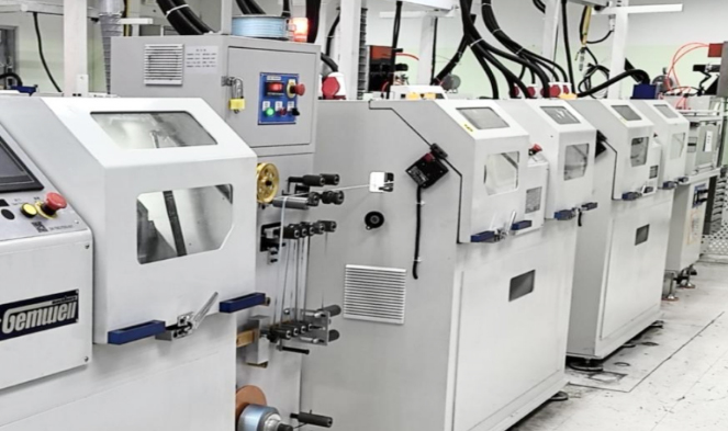
It begins with copper rod, drawn down through a wire drawing machine to the target AWG gauge. The drawn wire then passes through a wire and cable extruder, where thermoplastic insulation is applied. In a single-screw extruder — the most common type in cable manufacturing — the insulation compound is fed in pellet form into a heated barrel, melted, and forced through a crosshead die that coats the wire as it moves through. Line speeds for fine-gauge wire like 28 AWG typically run at 100–600 meters per minute, with the extruder's temperature profile and screw speed carefully controlled to maintain consistent insulation thickness.
After extrusion, the insulated conductors are assembled — either laid flat for flat cable construction or twisted in pairs for round cable construction. Twisted-pair configurations follow specific twist rates (turns per unit length) to control differential impedance. The assembled conductors may then be passed through a second wire and cable extruder to apply an overall outer jacket.
Connector termination follows: the cable ends are cut to length, stripped, and crimped or overmolded with the plastic SATA connector housings. The entire assembly is then tested for continuity, shorts, and in some cases high-frequency impedance characteristics using time-domain reflectometry (TDR) equipment.
This entire process — from wire and cable extruder line to finished cable — takes place largely in facilities across China, Taiwan, and increasingly Vietnam and India. The difference between a $2 cable and a $7 cable typically lies in which steps of quality control are performed and how tightly the wire and cable extruder process is monitored during production.
 Related Products