Home / News / Media information / Extruding Machine for Wire and Cable: How It Works & How to Choose

Media information

Extruding Machine for Wire and Cable: How It Works & How to Choose

Media information 2026-06-15

Content

Core Technology

What Is an Extruding Machine in Wire and Cable Production

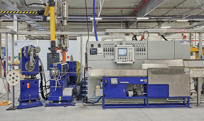
An extruding machine — specifically a wire and cable extruder — is the central piece of equipment used to apply a continuous layer of insulating or jacketing material onto a metal conductor. In practical terms, this means melting a thermoplastic compound such as PVC, XLPE, or LSZH inside a heated barrel, then forcing the molten material through a crosshead die that wraps it evenly around a moving copper or aluminum wire. The result is an insulated conductor produced in a single, uninterrupted pass at speeds that can exceed 1,200 meters per minute on fine-gauge data cable lines.

The extruding machine is the backbone of every wire and cable factory worldwide. Without it, raw copper or aluminum conductors cannot be insulated, and no finished cable — whether a power supply cord, a Cat 6A Ethernet cable, or a submarine high-voltage line — can be manufactured. Every wire and cable extruder performs the same fundamental task: converting solid plastic pellets or powder into a precisely controlled molten flow, then depositing that flow onto a conductor at consistent wall thickness, concentricity, and surface quality.

The critical distinction between a wire and cable extruder and a generic plastics extrusion machine is the crosshead die assembly. While a standard profile extruder pushes material straight through a fixed die, a wire and cable extruder redirects the melt 90 degrees (or in-line in some configurations) to surround a moving conductor. This crosshead design is what makes wire insulation possible at production speeds — and what makes the engineering of a wire and cable extruder both more complex and more specialized than any other category of plastics machine.

1,200m/min Max line speed for fine-gauge data cable
±0.01mm Dimensional tolerance on premium cable products
35–40% Share of cable insulation volume using PVC globally

How a Wire and Cable Extruder Works: The Complete Process

Understanding how an extruding machine operates from start to finish is essential for anyone evaluating, purchasing, or maintaining a wire and cable extrusion line. The process is continuous — unlike injection molding, a properly running extruder never stops mid-production — and each subsystem feeds directly into the next.

01

Pay-Off and Conductor Feed

The bare copper or aluminum conductor unspools from a reel on the pay-off unit, passes through a straightener to remove coil set, and optionally through a pre-heater that warms the conductor surface to 60–120°C. Pre-heating improves adhesion between the insulation and conductor, which is particularly important for XLPE power cable where the compound must bond to the metal surface.

02

Feeding and Plasticizing in the Barrel

Pellets or powder fall from the hopper into the feed throat at the rear of the extruder barrel. The rotating screw conveys the material forward through progressively hotter barrel zones — for standard PVC these range from 150°C at the feed zone to 180°C near the die. The screw geometry determines how thoroughly the compound is melted and homogenized. For PVC, a screw with an L/D ratio of 20:1 to 25:1 and a compression ratio near 3:1 is standard. XLPE for medium-voltage cable requires a longer 30:1 L/D screw to prevent premature crosslinking in the barrel.

03

Crosshead Die — Applying Insulation to the Conductor

The molten compound exits the barrel and enters the crosshead, where it is redirected around the incoming conductor. A torpedo or deflector inside the crosshead splits the melt flow and converges it evenly around the wire. Two tooling approaches exist: pressure tooling, where the melt contacts the conductor inside the die under pressure (used for insulation applications requiring adhesion, such as XLPE power cable), and tubing tooling, where the melt exits as a tube that draws down onto the conductor after the die (common for loose-fitting jackets on multi-core cables).

04

Cooling, Measurement, and Take-Up

The freshly insulated conductor enters a water-cooling trough. A 1 mm wall PVC conductor running at 200 m/min typically requires 20–30 meters of active cooling to solidify fully without dimensional drift. Laser diameter gauges, spark testers (1 kV to 15 kV depending on insulation class), and capacitance monitors run continuously inline. A capstan haul-off unit controls line speed with ±0.1% velocity precision before the finished cable is wound onto a take-up reel.

Types of Wire and Cable Extruder Configurations

Not every extruding machine is designed the same way. The configuration of the wire and cable extruder — single-screw, tandem, co-extrusion — directly determines what products can be manufactured, at what speed, and at what capital cost. Selecting the wrong configuration for a product range leads to quality problems, excessive downtime, or unnecessary investment.

Common wire and cable extruder configurations and typical operating parameters (Source: industry technical specifications from Davis-Standard, Rosendahl Nextrom, and Gemwell)
Extruder Type Screw Diameter Primary Application Typical Max Line Speed
Single-screw (smooth bore) 25–150 mm PVC insulation and jacketing Up to 800 m/min (fine gauge)
Single-screw (grooved feed) 45–120 mm HDPE, LSZH, PP compounds Up to 600 m/min
Tandem dual extruder Two screws, 45–90 mm each Dual-layer insulation and jacket Up to 500 m/min
Triple co-extrusion line Three extruders, 60–200 mm MV/HV XLPE with semiconducting screens 3–10 m/min (large power cable)
High-speed fine wire line (paired extruders) 30–45 mm per head Cat 6A, Cat 8, coaxial cable Over 1,000 m/min

Single-Screw Extruder: The Industry Workhorse

The single-screw wire and cable extruder accounts for the majority of global insulation production by volume. A 60 mm single-screw extruder running at 120 rpm can deliver 180–220 kg/h of PVC compound, enough to coat 1.5 mm² building wire at 400 m/min. The simplicity of a single screw-and-barrel arrangement means faster screw change for product transitions, lower spare parts inventory, and straightforward troubleshooting — advantages that large-volume building wire producers value highly.

Co-Extrusion and Tandem Lines: Multi-Layer Efficiency

For cables requiring two or more discrete layers — XLPE insulation with a bonded PVC jacket, or an automotive cable with a colored identification stripe over a white base compound — tandem or co-extrusion configurations feed separate compounds into a dual-channel or triple-channel crosshead. This eliminates the need for a rewinding pass between layers, reducing processing cost by 15–25% on multi-layer products. Triple co-extrusion is mandatory for medium-voltage XLPE cable, where the inner and outer semiconducting screens must bond to the insulation while still molten, with no contamination at the interfaces.

Materials Processed on a Wire and Cable Extruder

The compound family being processed defines the extruding machine's entire specification — screw geometry, barrel metallurgy, temperature profile, and cooling capacity. Different insulation materials behave very differently during extrusion, and running the wrong compound on an unprepared wire and cable extruder results in degraded output, high scrap rates, or equipment damage.

PVC

Polyvinyl Chloride (PVC)

PVC accounts for roughly 35–40% of all cable insulation volume globally. It processes easily between 160–190°C and accepts a wide range of plasticizer and flame-retardant packages. The key challenge is thermal sensitivity — above 200°C or under excessive shear, PVC degrades and releases hydrogen chloride, which corrodes the barrel and crosshead. Standard screws for PVC use a compression ratio of 2.5–3.0:1 with polished chrome-plated flights.

XLPE

Cross-Linked Polyethylene (XLPE)

XLPE is the standard insulation for medium-voltage (1–35 kV) and high-voltage power cables. The crosslinking reaction must happen after the die — not inside the extruder barrel — which constrains screw design to avoid excessive shear heating. Dry-cure nitrogen tubes maintain temperatures above 200°C for peroxide systems. Silane-XLPE systems use a simpler wire and cable extruder but require a post-extrusion sauna or hot water bath to complete the crosslinking reaction.

LSZH

Low Smoke Zero Halogen (LSZH)

LSZH compounds contain mineral fillers — aluminum trihydrate (ATH) or magnesium hydroxide — at loadings of 50–65% by weight, making them highly abrasive with significantly higher melt viscosity than PVC. Wire and cable extruders running LSZH require bimetallic barrels (minimum 60 HRC wear surface), hardened alloy screws, and larger crossheads. Output rates run 20–30% lower than equivalent PVC runs. LSZH is mandatory under IEC 60332 and EN 50266 fire standards for tunnels, marine vessels, and public buildings.

TPU

TPE and Thermoplastic Polyurethane (TPU)

TPE and TPU have grown rapidly in automotive, robotics, and portable tool cable applications, replacing vulcanized rubber in many high-flex uses. They are extrudable on standard wire and cable extruders with modest screw modification, process at 190–220°C, and eliminate the vulcanization step entirely. TPU offers outstanding abrasion resistance — 10 to 50 times that of PVC — making it the preferred jacket for drag-chain cables and industrial robot cables that flex millions of cycles in service life.

FEP

Fluoropolymers (FEP, ETFE, PTFE)

Fluoropolymer-insulated cables serve aerospace, military, and high-temperature industrial applications requiring continuous service at 150–260°C. FEP and ETFE are melt-processable on specialized wire and cable extruders with PTFE-lined melt paths or nickel-alloy construction, since fluoropolymers are corrosive to standard steel at processing temperatures of 340–380°C. PTFE itself requires ram (paste) extrusion rather than screw extrusion. Davis-Standard's dedicated fluoropolymer lines handle conductor sizes from 10 AWG to 30 AWG with wall thicknesses from 0.076 to 0.30 mm.

HDPE

HDPE and Foamed Dielectric Compounds

High-density polyethylene — both solid and physically foamed — is the insulation of choice for structured data cabling (Cat 5e, Cat 6, Cat 6A, Cat 8) and coaxial cable. Foaming with nitrogen injection or a chemical blowing agent reduces the dielectric constant from 2.3 (solid HDPE) to 1.5–1.8, which is what enables Cat 6A cable to reach 500 MHz bandwidth. Diameter control on a foamed insulation wire and cable extruder must be tighter than ±0.005 mm to maintain cable impedance within the ±3 ohm tolerance of TIA-568 standards.

Critical Quality Parameters That Define Extruding Machine Performance

Quality in wire and cable extrusion is not a single variable — it is the simultaneous control of several interdependent parameters, often through closed-loop automation on modern extruding machine lines. Understanding which parameters matter most, and how they relate to each other, is the key to running a high-yield wire and cable extruder operation.

Eccentricity and Wall Thickness Uniformity

Eccentricity — the off-center position of the conductor within the insulation — directly determines the cable's dielectric strength and its ability to pass high-voltage withstand tests. IEC 60227 specifies that for a 1.5 mm² PVC building wire with 0.7 mm nominal wall thickness, the minimum wall at any point must not fall below 80% of nominal. This means maximum allowable eccentricity is ±0.14 mm on a 0.7 mm wall. Achieving this consistently at 500 m/min requires a concentricity-controlled crosshead with die-centering bolts, an upstream conductor guide, and an in-line capacitance monitor feeding back to the crosshead actuators.

Melt Temperature and Melt Pressure Stability

Melt pressure at the die head is the primary real-time indicator of process stability on a wire and cable extruder. Pressure fluctuations caused by screw wear, inconsistent pellet feed, or worn screw flights appear directly as diameter variation in the finished cable. A stable extruding machine holds melt pressure variation below ±2 bar at steady state. Some precision lines install a gear pump between the extruder and crosshead to decouple screw output variation from die pressure, enabling diameter control to ±0.003 mm — a requirement for precision coaxial and fiber optic cable applications.

Barrel Zone Temperature Control

A typical wire and cable extruder barrel has four to six independently controlled temperature zones. For PVC, these rise from approximately 150°C at the feed zone to 180°C near the die. Precision PID controllers hold each zone within ±1°C, because a 5°C drift in melt temperature translates directly into viscosity variation and wall thickness scatter. Faulty heater bands and thermocouples are a common cause of temperature zone anomalies that are frequently misdiagnosed as compound or screw problems — preventive thermocouple replacement every 12–18 months is best practice.

Line Speed and Capstan Control

The capstan haul-off unit sets the draw-down ratio and directly controls the final insulation diameter. A servo-driven capstan with dancer roll tension feedback responds to diameter gauge readings within 50–100 ms on modern CNC line controls. Speed regulation better than ±0.1% velocity variation is essential for thin-wall insulation, where a 0.5% speed excursion produces measurable diameter change. Line speed is also the primary throughput lever: doubling from 200 to 400 m/min doubles output on the same extruding machine, so capstan stability directly impacts production economics.

Surface Quality and Spark Test Pass Rate

Surface defects — bubbles, pits, streaks, or rough texture — can result in electrical failures at spark testing. Bubbles are most often caused by compound moisture above 0.05% (solved by pre-drying pellets at 70–80°C for 2–4 hours) or volatile additives in the compound. Streaks typically indicate degraded material or contamination in the crosshead dead zones. The industry benchmark for volume insulation lines is a continuous spark test pass rate above 99.8% of all tested length.

Complete Wire and Cable Extruder Line Layout: From Pay-Off to Take-Up

A wire and cable extruder is never a standalone machine. It sits at the center of a complete extrusion line whose layout — from pay-off reel to finished cable take-up — determines startup scrap, changeover time, and final dimensional consistency. Total line length ranges from 20 meters for a small building wire insulating line to over 150 meters for a medium-voltage XLPE line with nitrogen cure tubes.

  1. Pay-off unit — holds the bare conductor reel (up to 3,000 kg for large power cables) with a tension-controlled dancer arm. Active pay-offs with servo drive maintain constant tension even during reel acceleration.
  2. Straightener and pre-heater — straightens coiled conductor and removes surface oxidation. Pre-heating to 60–120°C is standard for XLPE power cable to improve insulation adhesion.
  3. Wire and cable extruder with crosshead — the core unit. Barrel length, screw diameter, and crosshead bore are sized to the specific compound and product range being manufactured.
  4. Cooling troughs — typically two to three serial water-cooling sections with decreasing temperature (hot, warm, cold) to avoid thermal shock and residual stress in the insulation wall.
  5. Inline measurement — laser OD gauge, capacitance monitor, spark tester, and optionally an X-ray wall thickness scanner for precision cable products. All instruments feed data to the line PLC for closed-loop control.
  6. Capstan and dancer — servo-driven haul-off maintaining line tension and speed to better than ±0.1% velocity variation.
  7. Marking unit — inkjet or engraving unit applies meter marks, voltage ratings, color coding, and identification text to the outer surface of the insulation or jacket.
  8. Take-up and reeling — spool winder or drum twister, with automatic cut-and-transfer on accumulator-equipped lines to avoid production stops at reel changeover.

Misalignment between the pay-off and crosshead by as little as 2–3 mm at high speed causes conductor vibration and eccentricity spikes that are difficult to correct without a line shutdown. All units must be mounted on a rigid steel base frame and carefully aligned during installation.

Extrusion Defects on Wire and Cable Extruder Lines: Causes and Corrections

Even well-maintained wire and cable extruder lines encounter production defects. Recognizing the defect type and identifying its root cause quickly is the difference between a short correction interval and hours of scrap production. The table below covers the most common defects encountered on extruding machine lines across the industry.

Common wire and cable extrusion defects, root causes, and corrective actions (Source: Gemwell Electrical Machinery technical reference, 2026)
Defect Most Common Cause Corrective Action
Diameter variation (cyclic) Screw surge, worn screw tip, unstable melt pressure Install gear pump; inspect and replace worn screw components
Bubbles and voids in insulation Compound moisture above 0.05%; volatile plasticizer degradation Pre-dry compound 2–4 hours at 70–80°C; review additive package
Rough surface (sharkskin) Melt fracture from excessive die wall shear rate Increase die temperature; reduce line speed; add processing aid
High eccentricity Conductor vibration; misaligned die tip; worn guide tube Re-center crosshead; replace guide tube; check conductor tension
Streaks and discoloration Degraded material in crosshead dead zones Purge crosshead; disassemble and clean; inspect die dead zones
Spark test failures (pinholes) Contamination in compound; bubbles; thin spot from eccentricity Screen compound; address eccentricity issue; improve material handling cleanliness

How to Select the Right Extruding Machine for Your Wire and Cable Production

Selecting a wire and cable extruder requires working through a structured set of specifications before approaching any manufacturer. The wrong machine choice — undersized screw, incorrect L/D ratio, insufficient cooling, or inadequate line speed — cannot be fully compensated by operational adjustments. Define the following parameters before requesting quotations:

Conductor Size Range

Define minimum conductor cross-section (e.g., 0.1 mm² for data cable) and maximum (e.g., 300 mm² for power cable). This range determines the required crosshead bore size, die and tip selection, and whether a single crosshead can cover the full range or multiple crossheads are needed.

Compound Family and Wall Thickness

PVC, LSZH, and XLPE each require different screw geometry. The minimum wall thickness in the product range drives die and tip geometry selection and the draw-down ratio (DDR) target. Exceeding DDR 2.5 on LSZH can introduce melt fracture, resulting in surface failures on spark testing.

Target Output in kg/h

Calculate target output from line speed multiplied by the linear weight of the insulated cable at nominal dimensions. This calculation sizes the extruder screw diameter and drive motor. A 60 mm wire and cable extruder running at 120 rpm delivers approximately 180–220 kg/h of PVC compound — sufficient for 1.5 mm² building wire at 400 m/min.

Required Dimensional Tolerances

Standard building wire tolerances per IEC 60227 are achievable with basic diameter gauge feedback. Automotive cable per ISO 6722 or aerospace wiring requirements need a gear pump and X-ray wall thickness measurement. Define the tightest tolerance in the product range and size the instrumentation accordingly — retrofitting a gear pump after installation is possible but adds cost and downtime.

Number of Layers Required

Single-layer insulation uses one extruder. Dual-layer (insulation plus jacket) requires either a tandem line with two extruders in sequence or a co-extrusion crosshead. Triple co-extrusion for medium-voltage XLPE cable with semiconducting screens requires three extruders feeding a single three-channel crosshead — an entirely different platform from a building wire line.

Automation Level and Budget

A fully automated wire and cable extruder line with closed-loop diameter control, automatic reel change, and recipe management reduces startup scrap and labor cost by 30–60% compared to manual operation. Installed line prices for a general-purpose PVC/LSZH building wire line (60 mm extruder, 25:1 L/D, gear pump, laser gauge) range from $300,000 to $800,000 USD. XLPE medium-voltage triple co-extrusion lines start from $2 million and exceed $8 million for full dry-cure VCV vertical configurations. (Source: Gemwell industry reference, 2026)

Wire and Cable Extruder Applications Across Key Industry Sectors

The same fundamental extruding machine technology serves radically different industries, each with its own compound requirements, dimensional tolerances, and production economics. Understanding the application context is as important as understanding the machine itself.

Automotive

Automotive Wire Harness Cables

Automotive wire harness plants are among the most demanding environments for wire and cable extruder lines, with wire gauges ranging from 0.13 mm² to 6 mm² and line speeds of 600–1,200 m/min on fine gauge. Wall thicknesses as low as 0.15 mm on 0.13 mm² conductor demand diameter control to ±0.005 mm or better. Compound choices include PVC (standard), XLPE, and ETFE for zones near the engine requiring 125°C or 150°C continuous ratings. Color-coded insulation is critical for harness assembly, requiring inline colorimetric verification. Davis-Standard's automotive wire extrusion lines cover conductor ranges from 19 to 24 gauge for low-voltage signal and control wire.

Power Infrastructure

Medium and High-Voltage Power Cable

At the opposite scale, submarine power cable and extra-high-voltage land cable use the largest wire and cable extruder configurations available. Conductor cross-sections from 500 mm² to 2,500 mm² require triple co-extrusion lines applying the inner semiconducting screen, XLPE insulation wall (15–25 mm thick), and outer semiconducting screen in a single pass at 3–10 m/min. Insulation cleanliness at 220–525 kV cable class is extraordinary — metallic particles larger than 125 microns in the XLPE are prohibited, requiring ultra-clean compound handling and cleanroom assembly areas around the crosshead. With over 250 installed building wire systems worldwide, Davis-Standard is one of the recognized leaders for this segment.

Data and Telecom

Data and Telecommunications Cables

Structured cabling for Cat 6A and Cat 8 Ethernet, and coaxial cable for broadband distribution, prioritizes capacitance uniformity and impedance control rather than voltage withstand. Solid-core Cat 6A uses foamed FEP or solid HDPE insulation at 0.25–0.35 mm wall on 0.57 mm conductor, produced at 800–1,000 m/min. The foaming process — physical foaming with nitrogen injection or chemical foaming with azodicarbonamide — reduces dielectric constant from 2.3 (solid HDPE) to 1.5–1.8, enabling 500 MHz bandwidth. Diameter control on a foamed insulation wire and cable extruder must achieve better than ±0.005 mm to keep impedance within the ±3 ohm tolerance of TIA-568 standards.

EV Charging

Electric Vehicle Charging Cables

EV DC fast charging cables handle continuous current up to 500 A at 1,000 V DC, with bend radii below 30 mm at -40°C — a combination that demands flexible TPU or silicone jackets applied on multi-layer wire and cable extruder lines. Liquid-cooled designs add a layer complexity, with insulation extruded over a copper tube carrying cooling fluid. The extruding machine lines for this product must handle multiple simultaneous layers while preserving the flexibility properties that allow the cable to hang, recoil, and flex thousands of times in field use. Global EV charging cable demand is forecast to grow at over 20% CAGR through 2030, driving significant new investment in wire and cable extruder capacity worldwide.

Maintenance Practices That Extend Wire and Cable Extruder Service Life

A wire and cable extruder is a capital-intensive asset, with installed line costs from $300,000 to over $8 million depending on configuration. Proper maintenance translates directly to uptime, product quality, and service life measured in years rather than months. The practices below represent the standard adopted by high-throughput wire and cable manufacturers globally.

Screw and Barrel Wear Monitoring

Measure barrel bore diameter and screw flight diameter every 6–12 months using calibrated instruments. When diametric clearance between screw and barrel exceeds 0.4–0.6 mm (depending on screw diameter), output consistency drops and leakage flow increases, causing pressure fluctuations that appear as diameter variation in the finished cable. Replacing the screw before the barrel reaches the same wear stage is typically more cost-effective than replacing both simultaneously.

Crosshead Cleaning Frequency

LSZH and pigmented compounds require crosshead disassembly and cleaning every 8–24 production hours to remove degraded material from dead zones in the die and torpedo. Standard PVC natural compound on a clean line may run 200–500 hours between full cleanings. A scheduled purge cycle using a heat-stable purging compound before each shutdown removes residue without disassembly and extends the service interval significantly.

Heater Band and Thermocouple Inspection

Faulty heater bands and thermocouples cause temperature zone anomalies that are often misdiagnosed as compound or screw problems on the wire and cable extruder. Inspect heater clamps for loosening and hot spots quarterly. Replace thermocouples preventively every 12–18 months — the cost of a thermocouple is trivial compared to the scrap generated by a single temperature zone running out of control on an XLPE line.

Drive and Gearbox Service

Extruder gearboxes operate under high, cyclic torque loads. Follow OEM-specified gear oil change intervals, typically every 4,000–8,000 hours of operation. Vibration analysis on the gearbox twice per year identifies bearing wear before catastrophic failure. A gearbox failure on a high-speed wire and cable extruder line causes hours to days of unscheduled downtime and potential damage to the screw shaft.

Gauge Calibration and Spark Tester Verification

Laser diameter gauges require calibration against traceable reference targets monthly. Spark testers must be verified against a known artificial defect (a controlled pinhole in insulation) at the beginning of each production shift. An uncalibrated spark tester that misses real failures is more dangerous than no tester at all, because it creates false confidence in product quality while shipping defective cable.

Cooling Trough Water Quality

Cooling trough water accumulates biological growth, scale deposits, and plasticizer extractables over time. Biofouling inside a cooling trough can contaminate the cable surface with organic deposits that show up as surface streaks or adhesion failures. Maintain water conductivity, pH, and biocide levels within specification. Complete drain-and-clean cycles on the trough system quarterly, or more frequently on PVC lines where plasticizer extraction into the water is high.

Screw and Barrel Specification for Different Cable Compounds

The screw and barrel are the most mechanically critical components in any wire and cable extruder. Their geometry, metallurgy, and surface treatment determine output rate, compound homogeneity, pressure stability, and service life. Specifying the correct screw for the target compound family is not optional — running a PVC screw on an XLPE compound or an LSZH compound will produce quality problems that cannot be resolved by adjusting temperature or speed profiles.

Recommended screw and barrel specifications by compound family for wire and cable extruder applications
Compound L/D Ratio Compression Ratio Barrel Lining Screw Surface Process Temp Range
PVC 20:1 to 25:1 2.5–3.0:1 Standard bimetallic Chrome-plated, polished 150–190°C
XLPE 25:1 to 30:1 2.0–2.5:1 Standard bimetallic Nitride-treated alloy 200–220°C
LSZH/HFFR 25:1 to 36:1 2.0–2.8:1 High-wear bimetallic (60 HRC min) Hardened high-alloy steel 180–210°C
TPU/TPE 20:1 to 24:1 2.5–3.5:1 Standard bimetallic Nitride-treated 190–220°C
FEP/ETFE 20:1 to 24:1 3.0–4.0:1 PTFE-lined or nickel alloy Nickel alloy 340–380°C

The L/D (length-to-diameter) ratio is one of the most debated parameters in wire and cable extruder specification. Longer screws provide more residence time for melting and homogenization, which is beneficial for difficult compounds like LSZH with 50–65% filler loading. However, longer screws also increase shear heat input, which can trigger premature crosslinking in XLPE or degradation in heat-sensitive PVC. Some suppliers offer screws with an L/D of 36:1 specifically for physical foaming applications where precise material mixing and melting are critical. The right choice always depends on the specific compound being processed, not on a single universal recommendation.

v